Showing posts with label highway bridges. Show all posts

13 May 2021

Yorkshire Bridges: 33. Western Bank Bridge, Sheffield


Ah, it was good to get out and see an actual bridge again.

I'm not quite sure how I missed this beauty on my previous visits to Sheffield, but never mind.

It was built in 1969 to a design by Ove Arup and Partners and architect Yuzo Mikami. I say "it", but actually there are two bridges here, as shown in the cross-section below.


The bridges carry the steeply sloping A57 Western Bank highway above a pedestrian concourse area in the University of Sheffield campus. They are two-span structures, supported on single bearings below their tetrapodal centre pier, and a pair of bearings at each end.

The bridges were built in a period when the University campus was expanding, and the growth in road traffic had led to the highway being upgraded to a dual carriageway. Up to 10,000 pedestrians were reported to be crossing the road every day before the bridges were introduced.

The reinforced concrete slab decks vary in depth, being 1.2m deep over the central support and 0.84m at the abutments. It's a subtle feature that is not immediately obvious visually due to the large footway cantilevers on the edges of the deck.

Both decks are slightly curved in plan, but as can be seen in the photos, the main bridge deck slabs are straight, with the edge cantilevers varying in width to provide the curve.


From above, there is very little of interest to see. The interest is in the space created underneath the bridge. From below, this is a concrete roof held up on finger supports and providing some shelter from the weather. Glass blocks allow light through the central strip, and recently new lighting has been installed to make this a more attractive space at night.

It's a classic of modernist design, with some similarities to both Kingsgate Footbridge (1963) and Drochaid a' Chaolais Chumhaing (1984). The attraction is in its balance between the monolithic and the skeletal; it's clearly one "thing", like a sculpture, rather than one thing sitting upon another thing, like a conventional two-span road bridge.

The tetrapod supports have an interesting blend of straight and curved geometry: the outer edges form an inverted pyramid, while the inner surfaces of each arm are profiled with the curves of two intersecting hyperbolas. I'm not 100% convinced about the way the arms meet the deck slab and wonder whether a different detail would have been preferable e.g. having the arms project slightly from the side faces of the slab to give more of a "cradling" effect.

The sloping faces in front of the abutments were a conscious design choice, not so much to provide seating as to avoid the "tunnel" effect common to subways with vertical walls. The aim is to integrate the bridge with the adjacent landscaping. I guess the central tetrapods represent a similar visual impulse.

The block seating around the supports is not original. I wonder to what extent it was added to stop drunken students from bashing their heads into the angled support struts?

The concrete appears to have weathered well, and I'm left wondering why such a well-designed bridge isn't a little better known.


The article about the bridge in Arup Journal is well worth reading, including some excellent photographs, design drawings, explanations of the structural analysis, and an unexpected anecdote about students in mini-skirts.

The bridge was rewaterproofed, repaired and had new bearings installed in 2016.

Further information:

03 October 2019

Iceland bridges: 6. Hvítá bridge


This is the last bridge I'm going to feature from my Iceland trip, and it's the best.

When celebrating its 90th anniversary in 2002, the Association of Chartered Engineers in Iceland designated this bridge the most notable achievement of the third decade of the 20th century, the only bridge to make their list.


The bridge was built in 1928 by the national highway authority to a design by their engineer Árni Pálsson - it was one of the first projects in his career there, he went on to become their chief engineer in 1947.

The structure is 106m long, with two 51m span concrete arches spanning the river Hvítá (the "white river"). This structural form was chosen on cost grounds in preference to a two-span steel girder bridge or a one-span suspension bridge.

The structure carries the road Hvítárvallavegur between Hvítárvalla and Ferjukots. As you can see from the photo, this is a fairly rough highway, as with many in the country.

Prior to construction of the bridge, a ferry crossed the river, but this was unreliable when the river flow was high. Efforts to build a bridge began with surveys in 1910, and drawings were prepared in 1922, six years before construction eventually started.

The bridge would remain the main route from south-to-north in western Iceland until a bridge was completed downstream at Bogarnes in 1981.

The structure is instantly impressive, as attractive as many better-known concrete arches built in mainland Europe in this period. The 3m wide bridge was designed to carry a 6-tonne truck, or a uniform load of 400 kg per square metre (roughly 4 kPa), a similar load to what a pedestrian bridge would be designed for today.

The arch is very slender at its thinnest points, but unlike the broadly contemporaneous deck-stiffened arches of Robert Maillart (starting with the Flienglibach Bridge in 1923), it does not take its stiffness from the road deck.

The bridge draws its strength from the shaping of the arch - its connection to the deck at the middle of each span, and the thickening of the arch towards each support. This could have led to an ungainly appearance, but the sinuous profile of the upper arch surface combines well with the elliptical profile of the underside.


The set-back of the vertical support struts from the edges of the arch and deck also contribute to a fine appearance, emphasising the profile of the arch.

There are many more interesting bridges in Iceland, I only had time to visit a handful. Hopefully I'll get the chance to see more on a future trip!


Further information:

01 October 2019

Iceland bridges: 5. Jökulsárlón Bridge


This must be another one of the most-seen bridges in Iceland. It spans the outfall river from the Jökulsárlón glacier lagoon, and carries the island's ring road, route R1. You can't drive along the south coast of Iceland without eventually passing over this bridge.

The hengibrú (suspension bridge) was built in 1966-7, and has a main span of 108m. A ferry operated here from 1932, but before that the river was very difficult to cross.

I believe this was one of the last of a series of suspension bridges built in Iceland starting in 1945, and there are obvious similarities to the bridge over Jökulsá á Fjöllum that I featured previously, even though that is 20 years older.

When the bridge was built, the glacier Breiðamerkurjökull extended much closer to the highway. The glacier lagoon has grown steadily as the glacier has retreated, some 5.6km in the last century. This location, hugely popular with tourists, will at some point likely become the mouth of a new fjord, with the extent depending on how successfully global warming is tackled. Although efforts have been made to protect the foundations of the bridge against scour, it's lifetime may be limited.

Further information:

29 September 2019

Iceland Bridges: 4. Jökulsá á Dal Canyon Bridge


There are many arch bridges in Iceland, but this is probably one of the more unusual ones.

Built in 1994, this bridge is 125.5m long, with a main span of 70m. The steel-concrete composite road deck is supported on the arch via slender piers at 14m spacing.

The bridge was designed by Línuhönnun Consulting Engineers, who became part of EFLA Consulting Engineers in 2008. Swiss engineer Christian Menn was involved as a consultant.


The bridge is unusual for the arch being of composite construction, with a concrete slab supported on two steel box girders, and for its angular form. In the UK, we'd describe it as a "thrupenny-bit" profile. This solution was chosen over girder and framed options for aesthetic reasons, although studies showed a steel frame bridge to be slightly less expensive.

The composite form was chosen to eliminate the need for falsework as far as possible. The steel girders were erected first, and used to support 150mm thick prefabricated concrete panels. A further layer of in-situ concrete was then poured to create an arch 300mm thick in total. The width of the arch varies from 4.4m at the crown to 6.4m at its springings.

The bending stiffness of the arch and deck are similar, so in the finished bridge, they both resist asymmetrical bending equally.

The construction sequence had to be considered very carefully to ensure that the very slender arch remained stable at all stages - the construction photo below (taken from a technical paper describing the bridge's design and construction) shows quite how slender it appeared.


Further information:

26 September 2019

Iceland bridges: 3. Suspension bridge over Jökulsá á Fjöllum on Route 1


My journey took me east from the previous two bridges, following the Route 1 highway.

Iceland is well-supplied with large rivers, carrying meltwater from icecaps and glaciers. The Jökulsá á Fjöllum river appears wide but relatively unspectacular. However, the volume of water is substantial, as can be seen around 20 km to the north where the river spills over the enormous Dettifoss, reportedly Europe's largest waterfall.

Before there was a bridge here, the river could only be crossed by a ferry. The bridge was built in 1947, one of a number of suspension bridges completed within a 12 year period from 1945 to 1957, following Iceland's independence from Denmark.

The bridge is 171m long, with a main span 102m long and 3.7m wide. The steel ropes were supplied by British Ropes Ltd, and the steelwork was supplied and erected by Dorman Long.

The Icelandic roads authority have been planning a new bridge a little to the south of the existing structure, on the grounds that the existing bridge requires both speed and weight restrictions (lorries are forbidden by signs from travelling in convoy across the bridge). The new structure is proposed as a 5-span concrete box girder bridge, 230m long. Construction was due to start in 2015, but evidently it has been delayed.


Further information:

24 September 2019

Iceland Bridges: 2. Road bridge over Skjálfandafljót at Fosshóll on Route 1


This bridge was built across the Skjálfandafljót river in 1972, replacing an older truss bridge dating from 1930. The older bridge (and the remains of its 19th-century predecessor) can be seen in the photo at the end of this post.

Today, this structure carries Route 1, the main Icelandic ring road. Like many bridges in the country, it is only a single lane wide, although reportedly the national highway authority is considering building a new 2-lane bridge immediately to the north of this span.

As with many bridges in Iceland, it can best be described as pragmatic. The ladder-like inclined legs allow the main bridge girders to be more economical in size.


Further information:

10 April 2019

London Bridges series: 53. Holborn Viaduct

I suspect that for many people, Holborn Viaduct in London is known mainly as a street name rather than as a bridge: the street extends for around 425 metres (1400 feet) between Holborn and Newgate Street, but only a relatively short length of bridge is visible where the street passes above Farringdon Street. Elsewhere, most the street is hemmed in by buildings either side.


What can be seen today bears little resemblance to how this site looked in the past. What is now Farringdon Street was once the River Fleet, running north to south through a valley before spilling into the River Thames. The Fleet can be seen on the mid-16th century "copperplate map" of London, which also shows the old Holborn Bridge which then spanned the river.

Fleet Ditch was used as an open sewer, and was eventually covered over, section by section, and converted into a buried sewer. Today it remains there, running below the roadway down to the Thames.

Between 1863 and 1869, the entire valley was improved in a scheme designed by city surveyor William Haywood. The southern end of the scheme included the reconstruction of Blackfriars Bridge, while at Holborn, the old bridge was removed and replaced with what is now Holborn Viaduct. Haywood worked with engineer Rowland Mason Ordish on the viaduct's design.

Source: Grace's Guide

A contemporary drawing (above) shows the full extent of the Holborn Viaduct construction. Most of its length consists of brick arch spans, enclosed on their ends to form chambers, and in addition to the Farringdon Street structure, there are special spans over other roadways and railways. A drawing made in 1941 reveals the structure, exposed by bomb damage to adjacent buildings (below).

Source: drawing by Louisa Puller, via Wikipedia

Work on the new bridge started in 1867 and was completed in two years. The spans over Farringdon Street use paired cast-iron arched members supported on granite piers. The decking was originally constructed from cast-iron troughing topped in mass concrete.


On all four corners of the bridge, a large building was constructed to house a staircase connecting the upper and lower roadways. The one shown in my photograph is a post-war reconstruction, as the two north buildings were damaged by bombs during the Second World War.

The visible bridge is spectacular and ornate, and does make me wonder quite how its construction was funded. It is adorned with ornamental lighting, four statues (representing commerce, agriculture, science and fine art), and the ironwork on the main elevations is finely detailed and highly decorative.

From below, entrances into the masonry vaults can be seen, and perhaps income from letting these spaces and the staircase buildings helped contribute towards the cost of construction.

It can also be seen that the bridge has been extensively altered. By the end of the 1980s, the deck was found to be in poor condition due to water penetration, and calculations suggested the bridge to be seriously under-strength for modern heavy goods vehicle loads. DHV Burrow-Crocker Consulting (since merged into the Waterman group) were appointed to examine, assess and design improvements to the bridge.


The altered arrangement is visible in the photographs and explained in a diagram below taken from a 1993 technical paper. The existing decking was completely removed, and new steel-concrete composite decks inserted in between the cast-iron arch girders. The existing piers were extended upwards in reinforced concrete to encase the ends of the cast iron members, and the new bridge deck was supported via bearings onto the concrete extensions.


It's an exemplary piece of engineering, leaving the historic structure seeming largely unaltered from most point of views, and retaining most of the original fabric. The extensions to the piers are especially well-detailed, and I would not have noted them if I hadn't read the paper.

Further information:

30 January 2019

Upper Orwell Crossings project cancelled

Sometimes, it would be nice to have something positive to write about!

Welcome to what seems to be the final chapter in Suffolk County Council's Upper Orwell Crossings project. This started out in August 2016 as a scheme to build three new bridges across the River Orwell in Ipswich. The original cost estimate was in the region of £97m.


A RIBA-sponsored bridge design competition was held to appoint an architect to work alongside SCC's pre-appointed engineer. This struck me as being:
"one of the worst bridge design competitions to be organised in the UK for quite some time."
It turned out that I was not alone in this view. The main criticism was that the contest was an arranged marriage, with SCC picking an architect rather than an architect-engineer team. What if the architect and engineer just didn't get along? The selection process sought and evaluated designs (a total of five designs for three bridges, per entrant, to be precise), but was ostensibly to pick a designer, not a design. It also had a hefty price component, running the risk that a cheap and poor-quality designer could win against a more expensive but higher-quality designer.

A shortlist was announced in October 2016, several of the entrants either bringing along their own engineer or having in-house engineering expertise:
  • Adamson Associates (Toronto) with William Matthews Associates and Ney and Partners
  • Foster + Partners (London)
  • Knight Architects (High Wycombe)
  • Marc Mimram (Paris)
  • Wilkinson Eyre (London) with FHECOR and EADON Consulting
Foster and Partners were announced as the competition winner in March 2017, with the jury praising the "economic elegance" of the Foster design proposals.


It was clear from the press statements that SCC had picked what they felt would be a globally-recognised design. I drew attention to the RIBA Competitions office's poor track record at actually delivering bridge designs which went on to be built, and commented:
"Ambition should not be scoffed at, but I do wonder whether Ipswich really needs something world-class, or whether they would have been better to set their sights a little lower."
In April 2018, the Architects' Journal reported on an extensive investigation of the design competition, which showed that the exercise was, at best, poorly conducted, and at worst, actively unfair. There were some serious problems with the quality marking, but it was also reported that Foster and Partners revised and resubmitted their price before being awarded the work.

At this stage, I noted:
"I very much doubt that the designs shown at competition stage will be what is built, and in the absence of any meaningful cost or buildability evaluation, it's entirely possible they are beyond what Suffolk County Council can actually afford."
And now this is exactly what has come to pass.

In October 2018, a report was made public from another consultant, Jacobs, employed by SCC to review the project's status and capital cost. According to the latest estimates, the project's budget had increased to somewhere between £122m and £140m. It was apparent that notwithstanding the fuss around the Fosters design, SCC had quietly been developing a secondary design option in the background, a simpler baseline scheme termed by Jacobs the 'Do Minimum' option.

For the main span there was a £10m price difference between the 'Do Minimum' solution (£92m) and the Fosters tree-pier concept (£102m, pictured right). A number of other reasons are cited for cost escalation, none of them amounting to very much other than that the original estimate was too low (figures set before any design was actually undertaken), or that there was a failure to design to the available budget (this may have been impossible anyway).

The problem for SCC is that the project is, in financial terms, highly leveraged (or highly geared). Of the initial cost estimate, only £19m was to be provided by SCC, with the remaining £77m from central government. But central government funds were clearly stated as fixed, so any additional budget has to be provided by SCC. Even if the £122m figure is correct and does not rise further, that leaves SCC having to find £45m - more than double their original commitment, leaving a project they can no longer afford.

This is what also happened in the notorious River Wear Crossing project, eventually killing that scheme, which was also architecturally ambitious, beyond what was reasonable for the site.

Jacobs went on to identify a number of potential cost saving measures, most of them relying on ditching the competition-winning design, and in some options ditching one or both of the two smaller crossings included in the scheme. However, it appears that local politicians have little appetite for the bargain-basement alternatives.


SCC held a cabinet meeting yesterday at which they agreed to cancel the project, although they may still consider whether it makes sense to build only the two smaller bridges.

The papers prepared for SCC's cabinet meeting reveal that SCC have spent some £8.3m getting to this point, the bulk of it (£7.3m) on "external experts and contractors".

This is not quite as bad as the £40m reportedly thrown away on London's Garden Bridge, but you'd hope it's enough for local voters to ask some serious questions of their representatives.

27 January 2019

Johnson Street Bridge lawsuits

How time flies! I first covered Victoria, BC's Johnson Street Bridge some nine years ago, most recently writing about it again in January 2018.

Image courtesy Thedarkempire / Wikipedia

The project was initially controversial for the proposal to replace a 1924 historic heel-trunnion bascule bridge with a modern design. The new design was devised by MMM engineers with Wilkinson Eyre architects, and is a rolling bascule bridge, the largest such structure in Canada. Opposition from heritage groups was eventually defeated and the new bridge was completed and opened to traffic on 1st March 2018.

When I last reported, it was to discuss a dispute between contractor PCL, their client the City of Victoria, and the client's designers MMM. Wilkinson Eyre appeared to have long left the scene. There were also some really quite odd issues with the bridge's steel detailing.

The bridge has been back in the news again due to further legal disputes. These came to light late last year, with PCL filing a lawsuit against Victoria, MMM and design subconsultant Hardesty and Hanover. PCL have alleged that the designers provided a design which was late, incomplete, and contained errors; that the design was unreasonably changed; and they did not receive payments they were entitled to.

Some readers may recall that the contract was primarily traditional in nature, with the client responsible for providing the design, and the contractor building it. An odd feature of the procurement was that the contractor was obliged to value-engineer the client's design (PCL initially employed Hardesty and Hanover to help with this task).

Image courtesy Michal Klajban /Wikipedia

A key problem which seems to have haunted the project throughout its history is that the client's design was incomplete at the time that PCL tendered for the project, which is not normal practice in this kind of contractual arrangement. The contract setup is normally called "traditional" in the UK, or "design-bid-build" in North America, and the latter name indicates that the process is expected to be sequential, with the design complete before bids to build it are invited.

Local journalists suggest that PCL has merely lodged the lawsuit as a placeholder, a negotiating tool with the end aim of walking away from the project without any further liability on either side. This is based on a similar legal manoeuvre that took place in 2015/16.

A report in Focus on Victoria discusses the dispute but also draws attention to the general quality of the completed bridge. According to this report, some steelwork joints were sealed not by welding, but using a sealant material, which is already falling out. More interestingly, the bridge as-built is compared by Focus to the original design images from Wilkinson Eyre, such as the example below.


In the original design, large "ears" containing the bridge counterweights sit alongside the running rails on which the bridge rotates. However, both elements are blended smoothly together to give an organic appearance. With hindsight, it seems fairly clear that those flowing curves would be at best expensive and at worst impossible to fabricate, and likely to fall victim to the promoter's desire for value engineering.

Image courtesy Focus on Victoria

This picture shows what it really looks like, which is quite horrendous. There seems to be have been little thought about how to deliver a smooth curve in the steelwork, or even how to give the impression of one.

There's no manipulation here, either. The second image below shows just how disjointed the main steelwork trusses and counterweight ears actually are, with a physical gap between them on the outside face. To me, it looks quite bizarre.

Image courtesy johnsonstreetbridge.org

There are plenty of images on Google Streetview which show the issues as well.

Make no mistake: this is a remarkable bridge, with an interesting, exciting design. It's unfortunate that nobody was retained on the project with a brief to maintain the quality of the original design vision, and that the procurement process failed to find an acceptable balance between cost-cutting and quality.

Anyone who has worked on a complex landmark bridge project will know it can sometimes be a real battle to ensure an original idea isn't disfigured through messy compromise. Unless the client's commitment is there, it's difficult to resist negative changes. Even with a strong and imaginative client, success comes through all the team members pulling in the same direction, rather than being incentivised to do the opposite.

23 December 2018

Design published for new Polcevera viaduct


Details have been made public for the new Polcevera viaduct in Genoa, Italy, the proposed replacement for the bridge which collapsed in August this year killing 43 people.

The bridge design is credited to architect Renzo Piano, who offered his services free-of-charge in the aftermath of the August disaster. I imagine a structural engineer is involved, but I haven't found out who they are yet.


The €202 million construction contract has been awarded to Pergenova, a joint venture of Italian contractors Salini Impregilo and Fincantieri Infrastructure. They state that the new bridge will be complete in 12 months from the site becoming available, which will be when demolition of the existing structure finishes in March 2019.

The new structure is to be an elegant and, I think, consciously unspectacular steel viaduct, some 1.1km long, comprising twenty spans mostly 50m long, with some 100m long where required to span the railway and river. The reinforced concrete bridge piers are elliptical in section.


The design is sober and straightforward. The only nod towards the site's tragic history comes with the lighting columns positioned above each bridge pier. These extend in height and support a number of solar-powered lanterns, reportedly one for each victim of the bridge collapse.


I do wonder about the width of the piers - in some of the renderings, the deck is shown as much wider than its supports, which for me looks visually unsatisfactory, potentially unbalanced if only one side of the roadway is heavily loaded.

Of course, there will be no issue if the bridge deck is heavy enough, and Genoa is not in one of the more seismically active areas of Italy, classed as having a peak ground acceleration between 0.05g and 0.15g, for a 50-year return period, and from what I can see, at the lower end of this scale even for a longer 475-year period.


The Piano design was chosen against one other competing contractor, Cimolai, who submitted four proposals, three of them designed by Santiago Calatrava. The proposals featured a girder viaduct with a series of 125m spans; a cable-stayed viaduct with 140m spans; and a 550m-span tied arch bridge, all pictured below. You can find more detail in Cimolai's video and in a gallery on the Domus website.


It's no surprise that Cimolai were unsuccessful: which public authority would wish to run the risk of an over-budget fiasco at this particular site, as so often seems to accompany anything Calatrava designs? It's also apparent that any of these solutions would take longer to build than the Pergenova proposal.

Visually, two of the three lack a sense of lateral stability, and all of them are visually over-complicated and inappropriately dramatic. The arch design, with its awkward stiffening truss at deck level, is particularly poor.

Cimolai's non-Calatrava option (no designer appears to be credited), is worse still:


Meanwhile, some 20 people are reportedly under investigation on suspicion of involuntary manslaughter in connection with the original bridge failure.

18 July 2018

Welsh Bridges: 15. Devil's Bridge


So, Devil's Bridge, we meet again.

Well this is a different Devil's Bridge to last time. Two down, many more still to go!

Devil's Bridge (or in the local tongue, Pontarfynach) is one of the better known tourist attractions in the Aberystwyth area. Anyone can cross the bridge, as it carries a public road, but to see it properly requires payment to access private land. In addition to the bridge, this gives access to a very scenic woodland walk, and is well worth the price of admission.

The legend that gives this bridge its name is the same or similar to most other Devil's Bridge tales: an old woman's cow somehow crossed over the river Mynach, and she couldn't get it back. The Devil offered to build a bridge in return for the first living soul to pass across it, and the old woman agreed. She threw some bread across the bridge, and her dog ran after it. The Devil, having expected a higher price, had to be satisfied with the dog.

What I learn from this legend is that the old woman was pretty smart to give up the dog in return for getting her cow back. It must have been a very impressive cow to have jumped across the River Mynach gorge before the first bridge was built.

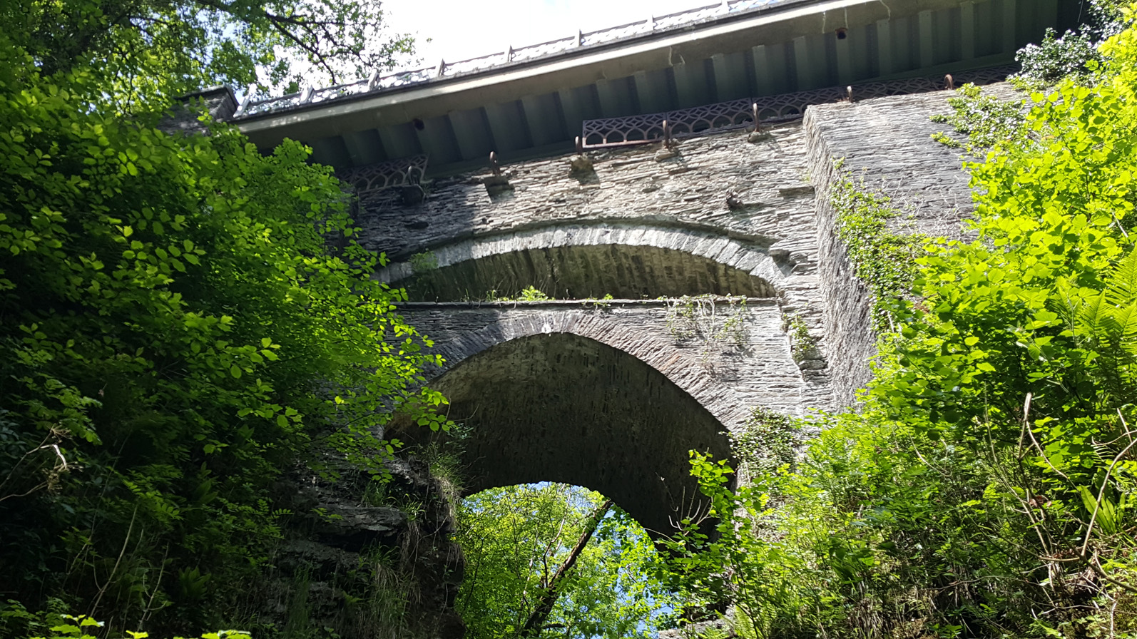
There are three bridges here, each one built above its predecessors. It goes one better than Rumbling Bridge, in Scotland, in that respect.

The lowest span is medieval, generally thought to date back at least to 1188, and comprises a pointed masonry arch sitting astride a remarkably deep cleft in the local rock, which contains the River Mynach (Afon Mynach). The most widely-held view seems to be that it was built by the monks of Strata Florida Abbey.

In Gwyndaf Breese's book on Welsh bridges, he suggests that the bridge reported by a traveller in 1188 was a "rickety wooden bridge", and that the stone span may have been built a century later.

Other than for its age and situation, it is relatively unremarkable. The arch barrel consists of thin bands of stone, springing directly from the rock. The profile of the barrel is noticeably distorted and unsymmetrical.

Breese quotes Jervoise in suggesting that the lowest bridge was widened or rebuilt at some stage. Jervoise's comment was that pointed arches were not in use in the 12th century, and the span must therefore have been a later reconstruction. I'm no expert but I don't think that is conclusive: the pointed spans in the medieval Exe Bridge are believed to be original, so why not here?

In 1753, a second bridge was constructed, a segmental stone arch spanning 32 feet. This bridge was later modified, with the height of its spandrel walls increased in 1814 to reduce the steepness of the highway approaches. It looks like you can see evidence of this in the banding of the horizontal stones in the spandrel walls. The ornate cast iron parapets were added at this time.

Buttresses at either ends of this span appear to have been added later. At one end of the bridge, the arch appears to spring from a higher point than at the other. Instead, it seems that the original springing is hidden within the masonry buttress, which continues under the arch barrel.


The third bridge was built in 1901 to a design by the County Surveyor Roderick Lloyd. Masonry abutments were built up to support steel lattice girders spanning 60 feet and carrying a 20-foot wide roadway.

This was substantially modified in 1971, when the castellated plate girders visible today were inserted along with a concrete deck slab. It looks to me that the parapets were designed to retain the appearance of the lattice girders, but clearly what's there now could not have been the original spanning trusses as there are no upper or lower chord members.

The newer girders are supported at one end on the abutment of the middle bridge, and at the other end on steel portal frames carrying the load to either side of that span. This was obviously an unfortunate period in the life of Devil's Bridge: the position, appearance and level of the new girders were all entirely unsympathetic to this span's predecessors.


Further information: