23 September 2020

Welsh Bridges: 18. Britannia Bridge


Thomas Telford built two significant suspension bridges on the north Wales coastline: the Menai Suspension Bridge (1819-1826), and Conwy Suspension Bridge (1822-1826). These formed part of a significant and much-needed improvement to the nation's highways. However, they were completed just four years before George Stephenson's Liverpool and Manchester Railway would kick start a very different transport revolution.

Roughly two decades after Telford did so for roads, it was George's son Robert Stephenson's turn to bring the railways to north Wales and Anglesey. He built two revolutionary bridges to span the exact same stretches of water as Telford: the Conwy Railway Bridge (1846-1849), and the Britannia Bridge (1846-1850). And just as had been the case for Telford, Stephenson could not do it alone.

The bridge across the Menai Strait was the most challenging element in the Chester and Holyhead Railway, and decisions on how to span the Strait remained unresolved while designs progressed for other parts of the line. Some thought was given as to whether the Menai Suspension Bridge could be modified to carry trains, but the loads required for a railway far exceeded those imposed by the horsepower that initially crossed Telford's bridge.

As in Telford's time, consideration turned to building a new arch bridge, but the Admiralty insisted on the provision of full clearance for high-masted ships across the full width of the Menai. Having settled on an alignment that made use of Britannia Rock in the middle of the channel, Stephenson proposed a flat span structure, with girders supported from above by suspension chains. The bridge towers were designed and then constructed tall enough to support such chains, although in the end they were never installed.


It seems that Stephenson conceived initially of a suspension bridge, and then sought a way in which it could be made sufficiently stiff to carry railway loads. He turned to William Fairbairn to investigate the feasibility of tubular stiffening girders, through which the railway tracks could run. Fairbairn rapidly came to the conclusion that the suspension chains would be too flexible, and should be dispensed with, but the less confident Stephenson kept provision for the chains until the bridge was complete.

Fairbairn undertook many experiments on tubular cross-sections, and in turn involved the mathematician Eaton Hodgkinson to analyse the experimental results. Stephenson's preferred girder design was for an elliptical cross-section, but Fairbairn soon determined that a rectangular section was more efficient. It rapidly became clear that buckling of the top flange of the girder was the key issue, a problem that was resolved by adopting a cellular upper flange to the girder, initially comprising two hollow circular tubes joined together, and later evolving into multiple cells side-by-side. 

Fairbairn constructed a 75ft span model tubular girder to resolve the final details of the rectangular tube design. The side walls required internal stiffening, and in the final design both the top and bottom flanges were made cellular. Although Fairbairn's experiments had been on single spans, the bridge was built as a continuous girder, giving it additional strength and stiffness.

Some of the other key participants in the project included Stephenson's assistant Edwin Clark, and Fairbairn's assistant Mr Blair, who was largely responsible for producing all the bridge's design drawings. After Fairbairn and Stephenson fell out in a dispute over recognition as being the true designer of the bridge, it was Clark who wrote the account setting out Stephenson's side of the story. Fairbairn published his own, and it seems generally to be regarded as the more honest version.

Credit is also due to architect Francis Thompson, who designed the masonry elements in a vaguely Egyptian style, as well as several other works along the railway. Thompson later worked again with Stephenson on Victoria Bridge, Montreal, another tubular bridge, as part of the Grand Trunk Railway in Canada.

Four sculptural lions were installed, one at each corner of Britannia, Bridge,sculpted by John Thomas, who also worked on the Palace of Westminster.

Hodgkinson had also fallen out with Fairbairn, essentially over the latter's willingness to extrapolate the results of his experimental work in the absence of a justifying mathematical theory. Around this time, Fairbairn began building many girder bridges with tubular (box) girders, but suitable theory was only just becoming available to practicing engineers. The sheer scale of the Britannia structure went well beyond what had been attempted previously - just as Telford's Menai Bridge had done a quarter of a century before.

The project innovated in many ways. The extensive reliance on wrought iron was pioneering, and the span was exceptional for a flat-span bridge. The range of experimental work relied upon was impressive, as was the idea for the cellular construction. Even the erection of the bridge required major innovation, with the girders lifted into place by jacking upwards with massive hydraulic jacks. The slots for the jacking process remain visible on the towers, and part of one jack can still be seen near the bridge on its south-west side.

Two million rivets were reported to be used, with workers having to squirm through the box cells to install many of them. This, more than anything else, determined the size of the cells used.

On 24 May 1847, while construction of the Britannia Bridge progressed, one of Stephenson's other railway bridges collapsed, killing five people. The bridge over the River Dee near Chester was constructed of three cast iron girder sections connected with wrought-iron link bars. It was a popular design at that moment of time, with at least thirty-four built prior to the Dee failure. Fairbairn had proposed in 1846 that Stephenson should use a wrought-iron tubular girder bridge across the Dee, but had been turned down.

This incident exposed Stephenson's lack of expertise as a structural engineer, and Fairbairn's views prevailed both at Britannia and more widely - he was involved in over 100 more tubular girder bridges (albeit predominantly with the girders sitting beside the tracks, rather than containing the tracks) within a 5 year period.

While the tubular girder was successful in the short-term for short and medium span bridges, it was not the optimal solution for larger structures, and the Britannia Bridge design would prove a dead-end. Before long, various forms of lattice-girder and truss bridges took over, although early lattice-girder railway bridges experienced their own problems. For more detail I can wholeheartedly recommend John Rapley's and Richard Byrom's books (see list of references below), both of which are excellent.

Britannia Bridge was bold, if not entirely beautiful, but I think there is a great deal to admire in its simplicity of line. It lasted 120 years until, on 23rd May 1970, a fire broke out, irreparably damaging the bridge's two tubular girders.


The replacement bridge seen today was built between 1971 and 1974, with two main truss arch spans over the Menai Strait. Both Telford and Stephenson had considered arch bridges, and finally the navigational restrictions that had forced both into bolder and more innovative designs were no longer an issue.

The form of the present-day bridge, designed by Husband and Co. (merged into Mott, Hay and Anderson in 1989, now Mott MacDonald), owes a great deal to the challenges of safely dismantling the damaged tubular girders, as well as to the need to reinstate a railway line as quickly as possible. 10,500 tons of metalwork had to be removed, forming a load well in excess of the railway traffic that the replacement structure would carry, and the arches were therefore designed and sized primarily to act as support to the demolition operation. Once the tubes were safely and temporarily supported, railway services were reopened through one of the damaged tubes in January 1972. The tubes themselves were cut into short sections, and then hauled off the end of the bridge using small locomotives.

The bases of the towers were extended with small concrete skewbacks to carry stainless steel pins, which carry the entire load of the new bridge. The steelwork for the new arches was assembled by Cleveland Bridge four miles from the bridge, at Port Dinorwic, and floated into place on barges.

The spans were cantilevered outwards from the central tower, with adjustable tie bars passing through the tower to provide temporary support. Lifting gantries moved along the upper chord of the arch truss to lift each new truss unit into place, as can be seen in the construction photograph below (taken from a souvenir booklet about the bridge).


During construction, the arches each briefly formed a three-pinned arch before pre-load was jacked into the upper member to transform the whole system into a two-pinned arch.

Because the arches had capacity well in excess of railway loading, this created the opportunity to add a second deck to carry highway loading, and openings in the towers were enlarged to facilitate this. The railway bridge was finished in 1974 (albeit with only one deck carrying services, as railway traffic was much diminished), and the road deck eventually completed by Fairclough Civil Engineering and Fairfield Mabey in 1980.

The steelwork for the new railway bridge weighed less than half of Stephenson and Fairbairn's original wrought iron bridge, only 4,961 tons, although the road bridge (which is nearly twice as long as the rail bridge) incorporates another 4,338 tons of steel.

Although it is often noted that the ordinary observer prefers an arch bridge over any alternative, the modern bridge is, to my eyes, less loveable than the original. Partly this is because of the sheer quantity of truss bracing, and partly that the visual relationship between road and rail decks is uncomfortable. I think this is partly due to the sheer depth of the edge beams at railway level.

On the plus side, the history of the bridge is there to be seen. The excess tower height originally intended to carry suspension chains contributes to the support of the road deck and punctuates the span in a pleasing way (compare Sydney Harbour Bridge). The form of the arches betrays their origin as falsework for a demolition process. The preserved cross-section of  tubular girder (accessible via a path leading to the south-west corner of the bridge) is well worth visiting. The masonry still looks excellent today, and the bridge's best-kept secret, the "cathedral" vaults at each end, are still intact albeit normally inaccessible.


Further information:

20 September 2020

Welsh Bridges: 17. Menai Suspension Bridge


Where do you start when trying to write a simple blog post about a bridge like this? So much has already been written (see links at the end, which are selective and do ignore some of the more detailed publications)!

The first serious proposal for a bridge over the Menai Strait came in 1802, when John Rennie proposed a multi-span viaduct of masonry and cast iron. A few years later, in 1811, it was Thomas Telford's turn, presenting designs for either a multi-span cast iron viaduct similar to Rennie's or for a single cast-iron span. Neither of these ideas were adopted.

Telford revisited the site in 1818, and prepared plans for a suspension bridge instead. Construction work began on 10th August 1819, three years ahead of Telford's suspension bridge at Conwy. Both bridges were completed in the same year, 1826.

The bridge at Menai became the longest bridge span in the world, its 577 feet length exceeding the 449 feet of Samuel Brown's Union Chain Bridge, completed six years earlier in 1820. Brown's bridge had commenced construction only a few days before the Menai bridge, on 2nd August 1819, but was built much more quickly than Telford's bridge.

Menai Suspension Bridge held the span record for 8 years before being overtaken by the 889ft Fribourg Suspension Bridge, in  October 1834, a month after Telford's death. It's maybe worth noting as a historical aside that the Union Chain Bridge's earlier record is attached to some degree of doubt: the 1430 Chushul Chakzam footbridge in Tibet may have been a very similar span, although records are poor.

The Menai Bridge's span was a remarkable achievement, and if it isn't Telford's finest bridge, I think it's the most substantial engineering challenge that he ever took on.

Telford had been looking at suspension bridge ideas since 1814, when he was commissioned to develop a proposal for a road bridge at Runcorn. That design was for what would have been an astonishing 1000ft span, something that would not be achieved on any bridge until 1849. Telford proposed to form the Runcorn bridge's catenaries out of half-inch square iron bars, welded and bound together into sixteen "cables" each comprising 36 such bars. He arranged for extensive testing of the strength of iron to inform the design, and built a model suspension bridge 50ft long.

The promoters of the Runcorn crossing invited others to submit designs for review by Telford. The only submission to meet his approval was a suspension bridge proposal from Samuel Brown, who proposed catenaries comprising iron chains. Telford visited Brown's factory in February 1817, where he was driven across Brown's own model bridge, albeit quite a substantial model some 100ft in span. At the time, Brown was working with chains made from iron rods, as he was to use for the Union Chain Bridge, although he also developed chains made from flat iron plate.

The Runcorn bridge was never built, but when invited to develop the Menai crossing, Telford at first continued with his idea of square iron bars welded and bundled to form cables. Perhaps he was influenced by Brown's patenting his own chain bridge ideas in mid-1817. It was only later, as work proceeded on the masonry parts of the Menai bridge that Telford switched to flat-bar chains, supplied by William Hazledine. There were to be sixteen chains in total, with four groups of four chains arranged vertically above each other; one group at each edge of the bridge, and two on the centreline of the roadway. There is a good image showing the original suspension arrangement at Wikimedia Commons.

Incidentally, it is sometimes claimed that Telford sought permission from Sarah Guppy to use her 1811 patent for suspension bridges. Guppy's patent appears to have been for a catenary bridge, with the decking laid directly onto the suspension bridges, not for the type of bridge that Brown and Telford pursued. There seems to be little substance to this claim, but Telford certainly did rely very much on the assistance of others. Examples include learning from Brown's success in pioneering the use of iron chains; Hazledine's manufacturing capabilities; Telford's right-hand engineer William Provis; Peter Barlow's advice on the strength of iron; and Davies Gilbert's understanding of the mathematics of the catenary.

Telford's bridge encountered problems almost as soon as it was complete. Strong winds caused damage to the timber deck and to the hanger bars just one week after it opened. Remedial works were completed, but a storm in 1836 caused huge oscillations and significant damage, and then in 1839 another storm left the deck in ruins and the bridge impassable. Provis was employed to design a stronger, heavier deck.

Issues with wind on suspension bridges were by no means unique to Menai. Similar issues occurred around the same time on Samuel Brown's South Esk Bridge in Montrose, and wind-induced oscillation was also observed at Gattonside Bridge. Telford had not been unaware of the issue, and before the bridge was complete he was reported to have considered stiffening the deck with trusses, deciding eventually that if ever required, they could be retrofitted. The Menai Bridge was a giant engineering prototype, and as with any experiment, its performance was never entirely foreseeable.

The strengthened bridge lasted until 1893, when a new steel deck designed by Sir Benjamin Baker was introduced, largely to resolve problems with the deteriorated state of the timber deck. Further investigation and remedial work took place on several occasions before a decision was made that the bridge could no longer safely carry the loads required.

Between 1938 and 1940, the metal parts of the bridge were completely reconstructed, to a design prepared by Sir Alexander Gibb and Partners, and consultant Guy Maunsell. If the work had not already been underway, it's impossible to imagine it would have started once the Second World War began, given the quantity of steelwork involved and other demands for skilled labour. In any event the bridge was completed, but Maunsell was rapidly immersed in the war effort, turning his engineering skills towards sea forts and the concept behind the floating Mulberry Harbours. Due to the needs of wartime secrecy, his account of the Menai Bridge reconstruction was only published after the war had ended.

The masonry approach spans, which are themselves impressive structures, were left unaltered. Works were undertaken on the upper towers to slightly widen the portals through which vehicles pass. The masonry Bridge Master's House at the southern end of the bridge had its upper parts rebuilt to accommodate replacement of the suspension chains.

The suspension chain alterations included reconstruction of the anchorage elements hidden within tunnels at each end of the bridge. Temporary suspension cables were installed at the edges of the structure to relieve the load on the outer chains. The original sets of four chains directly above each other were replaced with sets of two chains directly above each other, with larger links in much stronger steel.

A new deck was constructed below the existing deck, to allow traffic to continue to use the bridge during the works. The existing deck was then removed (one lane at a time), allowing traffic to drive up and down ramps onto the lower deck. Once this stage was complete, the new deck was gradually raised into its final position. The original centre chains were removed entirely, with the only real evidence today of their existence being the empty slots in the face of the former Bridgemaster's House. The new edge trusses were then completed, considerably enhancing the load carrying capacity of the bridge.

I doubt that casual visitors to the bridge see it as anything other than Telford's structure. The profile remains the same, including the strange back-span arrangements where the chains are anchored directly down into the approach viaducts with hanger bars. Given the over-riding need to enhance the traffic capacity of the highway, the reconstruction was a relatively sensitive project. Even retaining chain catenaries was a technologically unusual choice in the mid-20th century: nobody was still building chain bridges at that point in time.

The trusses were foreseen by Telford, and don't mar the overall appearance of the structure, although the tacked-on cantilever footways are narrow and the new parapets feel over-tall. The detailing of the footway widening on the approach viaducts gives the impression that it was always there.

The bridge now provides one of the best viewpoints in the vicinity, and is one of the UK's most significant engineering landmarks. As with many such large bridges, it has come to define the character of the Menai Strait, visually structuring the way that visitors experience the area as well as remaining a key transport link.

Another bridge was built in 1850 to carry the railway across the Strait (later converted to become the main highway in the 1970s), and plans are under consideration for a third crossing. As with the Forth in Scotland, the prospect of a "family" of bridges is enticing, although it is too early to tell whether the new plans will be as visually successful.


Further information:

16 September 2020

Manchester Bridges: 24. Brabyns Park Bridge, Marple

Now here's a tale of woe.

Nathaniel Wright exemplified the manner in which the industrial revolution wrought huge changes on British Society at the end of the 18th and beginning of the 19th century. He made his fortune from coal mining in Derbyshire, and associated closely with other entrepreneurs such as Samuel Oldknow, who was the main driver behind construction of the Peak Forest Canal, connecting the Derbyshire coal mines through to Manchester.

In 1800, while the Canal was just finishing work on Benjamin Outram's Marple Aqueduct, Wright purchased the Brabyns Hall estate nearby. The estate lies immediately to the east of the Peak Forest Canal, occupying the land between the canal and the River Goyt. As one improvement to the estate, Wright commissioned Salford Iron Works to construct a bridge across the river, providing access to and from nearby Compstall village. The Salford firm's engineers James Bateman and Thomas Sherratt had previously in 1795 supplied a pumping engine for one of Wright's collieries.


The new bridge was in the form of a cast iron arch, possibly the first such bridge in this part of England. The design was broadly patterned after Thomas Telford's 1797 Cound Arbour Bridge, with three cast iron arch ribs, each with a series of iron circles filling the spandrels. Variations on this theme were common, another example being the 1810 Tickford Bridge, but Telford had moved on, using the more rational diamond-pattern spandrels in his 1814 Craigellachie Bridge, for example.

The bridge is decorated with the date and name of its maker, and the lightweight iron parapets feature an ornamental "W" in the middle, for the owner Wright, who died five years after the bridge's completion, in 1818.

So far as is known, the Brabyns Park span is the only bridge to have been built by the Salford Iron Works. It spans approximately 14m (46ft) and is 2.7m (9ft) wide. The central rib was cast in two halves, joined in the middle. The external ribs were cast in six pieces, with each half subdivided into three parts: an upper rib, a lower rib, and the circular spandrel elements. The arch ribs were stabilised by tie bars at their lower level, and by cross-bracing at the upper level. The original decking comprised timber planks.

 In 1991, a structural assessment of the bridge labelled it dangerous, and a "temporary" bailey bridge was installed directly above it, remaining there until 2007, when the bridge was finally refurbished, following a lengthy campaign. Photographs of the bridge taken in 2007 immediately prior to refurbishment show the bridge to be horribly neglected, although how much of that was due to the difficulty of maintaining it with the bailey bridge in the way is hard to tell.

The bridge is Grade II Listed, but it was a lengthy battle to secure Heritage Lottery funding for its restoration, and then to agree exactly what works would be carried out. A design by engineers Scott Wilson Kirkpatrick (now submerged into AECOM) was eventually accepted after much debate.

In 2003, the campaigners had commissioned a report by local engineering lecturer and historic bridge specialist Tom Swailes. According to the report, the main issue with the bridge when it was closed in 1991 was the condition of the timber decking. Swailes took the view that:
"Future loads on the bridge will be no greater than the loads that it safely carried for 178 years. It is interesting to apply modern computer-based structural analysis techniques to old structures, but the results of such theoretical analyses must almost always be disbelieved unless verified by tests on the structure itself."
The subsequent involvement of "proper" consulting engineers seems to have been a curse. The designer's drawings proposed significant alterations to the bridge, over and above what may have been required for simple restoration. As Swailes noted in his report, despite its neglect the bridge had stood the test of time.

That was clearly not enough. The main structural alterations involved the bonding of steel plates to the central arch rib, the renewal of corroded bracing elements and the addition of new transverse bracing between the arches. These have relatively minimal impact on the appearance of the bridge, and you may struggle to see them on my photographs. In any event the underside of the bridge is not seen by most people, and is difficult to view even from the river bank.

The larger issues for the engineers (or for the technical approval authority at Stockport Council, perhaps), were the presence of a gas main, a small water main, and electric cables, which seem to have been previously laid on top of the deck planks; and the height and strength of the existing parapet railings, which were now judged to be inadequate.

Measuring from the engineer's drawings, the original parapets are approximately 1.15m tall (although it will have been less when fill material had been piled onto the bridge decking to cover the gas main). This could not possibly do, the parapets had to comply with modern standards and be 1.4m tall (the modern requirement for cyclists). The solution to this, and also to accommodating the utilities, was to install new parapets connected to steel hollow sections sitting entirely on top of the existing bridge, with the hollow sections also used to contain the utilities.

The campaigners were evidently not very happy. On their website they indicated their regret:
"This means that in the future, perhaps with technological improvement or an enlightened approach to safety standards, or a combination of both, the modern intervention could all be removed and the old bridge will be revealed intact underneath."
No such technological improvement was ever needed: simply an "enlightened approach" that recognised that an existing historic structure could be considered to be perfectly acceptable whether or not it complied with modern standards. Nobody is going around rebuilding ancient castles (or installing 1.4m tall balustrades on the battlements) simply because the original builders couldn't foresee the stupidity of 21st century compliance-drive engineering culture.

Quite what the local planning authority, or English Heritage (now Historic England), thought is difficult to say. They certainly should have demanded that the engineers think again. Reading through the excellent restoration campaign website, one thing that jumps out at me is the absence of any mention of a specialist conservation engineer or conservation architect. The result, in my opinion, was deeply unfortunate.

The new parapets are painted a different colour to the original bridge, with a view to disguising them when the bridge is viewed from a distance. I don't think it succeeds: the elevation of the bridge is intact but the parapets are hard to miss. Seen from the perspective of crossing the bridge, the visual impact is much worse, essentially ruining what was a fine and historic structure. Reaching over the new parapets to push against the old ones, it seemed to me that the original parapets were quite strong enough.

The difficulty with hoping that this can be put right in the future is that not only was the opportunity lost at the time when funding was available, but that so much of the funding was seemingly unnecessary. It is perhaps unfair to criticise those involved when not in possession of all the information that they had, but at best the treatment of the Brabyns Park bridge is a crying shame, and at worst it's the inevitable but disastrous outcome of foolishness and incompetence.

Further information:

13 September 2020

Derbyshire Bridges: 5. Headstone Viaduct

This will be my final "Derbyshire Bridge" for now, and this one is a well-known historic classic, Headstone Viaduct, also often known as Monsal Dale Viaduct. It is the star of a famous London Midland and Scottish Railway poster used to attract tourism to the Peak District, depicting a deservedly spectacular location (albeit with some artistic license!)

The viaduct was completed in 1863 as part of the Midland Railway company's Manchester, Buxton, Matlock and Midland Junction Railway. This railway has a long and complex history, which (if so inclined) you are better off reading at Wikipedia than I am repeating in any detail here. Suffice to say that the route connected Derbyshire to Manchester through the hilly terrain of the Peak District, and substantial civil engineering works were required.


It seems a wonder now that there were ever funds available to build a railway through such difficult terrain, necessitating not only major viaducts but a number of substantial tunnels. Perhaps it is worth imagining what the nature of the highways of the time must have been, for this to have been an attractive alternative.

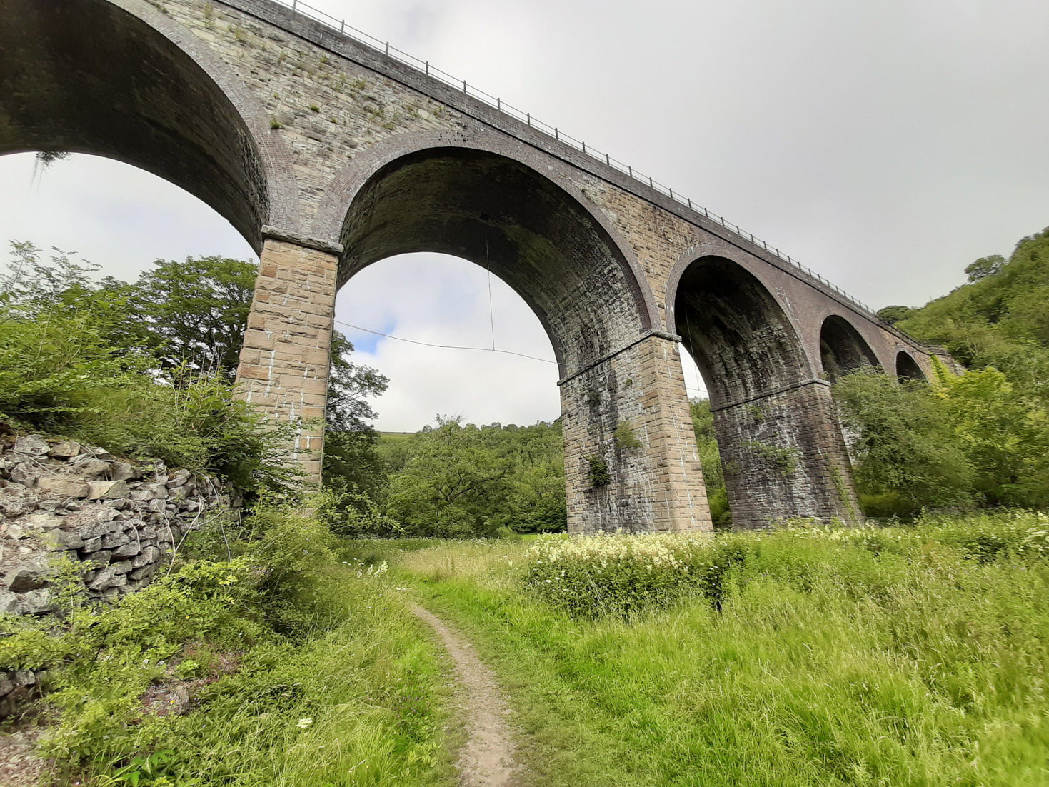
The viaduct has five arches each spanning 50 feet (15.5m), and is roughly 25m tall. It originally carried two railway tracks, emerging from a tunnel in the steep hillside to the east and then passing along the flank of another hill to the west.

The railway was closed in 1968, and the route was converted to the Monsal Trail for cyclists and walkers in 1981. The closest you can come now to reliving the steam train experience would be to hurtle westwards on a bicycle at speed from the tunnel mouth into the open air, taking in the views with a sense of astonishment and relief.

The viaduct design has been credited to William Henry Barlow, perhaps best known for the design of another Midland Railway project, the St Pancras train shed. Headstone Viaduct is far from his most notable bridge: along with John Hawkshaw, he completed Brunel's Clifton Suspension Bridge, and he also designed the replacement for Thomas Bouch's ill-fated Tay Bridge. However, Midland Railway engineer Frederic Campion may have held more direct responsibility.

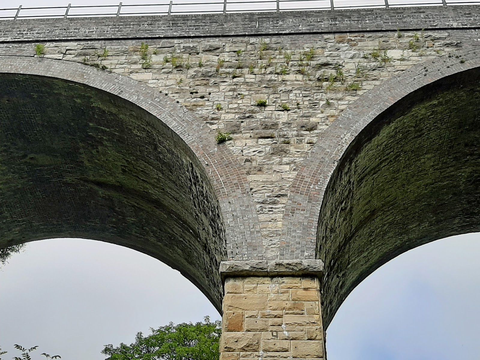
The construction of the arch barrels is a little peculiar. The facing voussoirs on each arch comprise seven rings of brickwork (an inner two bonded together, and then five outer rings), down to springing level. The piers and spandrel walls are in rubble stonework, and stone is also used for the lower part of the inner face of the arch barrel. The upper parts of the arch barrel are in brick. It seems an odd arrangement.

Brickwork is also extensively employed above two arches on the south elevation, possibly associated with remedial work completed in 1907-8. I doubt that many visitors notice!

The overall impression is robust but not excessively so - the scale and nature of the bridge is entirely appropriate to its setting. It's interesting to wonder what would be built if a similarly beautiful valley were to be crossed by a new railway today.

The Victorian polymath and art critic John Ruskin (something of a 19th century Brian Sewell) certainly didn't appreciate either the railway or the viaduct, writing:
"There was a rocky valley between Buxton and Bakewell, once upon a time, divine as the Vale of Tempe ... You Enterprised a Railroad through the valley - you blasted its rocks away, heaped thousands of tons of shale into its lovely stream. The valley is gone, and the Gods with it; and now, every fool in Buxton can be in Bakewell in half an hour, and every fool in Bakewell at Buxton; which you think a lucrative process of exchange – you Fools everywhere."

As is often the case, age provides architecture not only with grace, but it also elevates the perception of the location as a whole. Without the viaduct, this could just be any other pretty green Pennine dale. The viaduct is the centrepiece, the thing that visitors peering down into the valley from above all point their cameras towards.

It also provides a fine platform from which to view the surrounding greenery. Many visitors descend the path from the nearby Monsal Head car park to admire the viaduct and the tunnel entrance without going any further. An encounter with England's green and pleasant land need not require a lengthy trek.

It is certainly worth taking the time to go a little further and follow the path below the viaduct. From above it is impressive, but dwarfed by the surrounding landscape. From below, the opposite is true, it is a stone giant soaring overhead, framing shorter views and guiding the curious visitor eventually to the banks of the River Wye, ultimately responsible for carving this landscape over unimaginable years past.

It has obviously been a site for a more interactive visitor experience in the past. Signs on the viaduct draw attention to metal bars, suspended from the arches and stretched between the stone piers. These are intended to prevent people from leaping off the viaduct attached to a rope and swinging underneath. Certainly nobody was trying it when I visited.

Part of the railway line was reopened as a "heritage" service in 1992. There are broader ambitions to reopen the whole route as a "proper" railway, with Monsal Trail "reprovisioned", whatever that means. Personally, I think it would be a real shame if it denied people the chance to get up close and personal with the trail, its tunnels and viaducts.


Further information:

09 September 2020

Derbyshire Bridges: 4. Railway Viaduct, Edale Road, Hope


This is another 1970s structure built to replace one of the original bridges on the Hope cement works railway line (for context on the railway, see my earlier post).

The original 1929 bridge was a reinforced concrete trestle structure 347ft (106m) long, with eight spans of varying length. A 13ft (4m) wide deck slab spanned onto rail-bearers and crossbeams, which were supported from raised concrete girders on both edges of the deck. These then sat on reinforced concrete columns, braced with horizontal members to create H-frames.

The viaduct actually consisted of two structures, with a double-trestle in its middle and a copper expansion joint separating the two. The end trestles were buried within approach embankments, and will have provided stability against longitudinal loads from the railway. There is an image in Concrete and Constructional Engineering magazine which shows the finished viaduct:


There is also a photograph on designer Geoff Bond's website showing the 1929 structure hidden behind the new bridge, presumably pending demolition.

The present bridge is a 5-span post-tensioned concrete viaduct, carrying the railway over the Edale Road and the adjacent River Noe. I think it looks rather elegant in an artist's impression from 1973.

The main feature that makes it unusual is the way in which the lower flange of the box girder is extended outwards. Normally, such bridges extend only the upper flange (to form the road or railway deck), there is no obvious benefit to complicating things by extending the lower flange. Geoff Bond was a member of the design team at Oscar Faber and Partners, and his website indicates that the rationale was "to resist reverse bending moments and severe locomotive shear stresses".

I'm left slightly puzzled, and would love to have been able to find more information.


Further information:
  • Google maps
  • Reinforced Concrete Bridges in Derbyshire (Concrete and Constructional Engineering, 1929)

06 September 2020

Derbyshire Bridges: 3. Hope Catenary Footbridge

This bridge carries what is now a public footpath across the Breedon Cement works railway line in Hope. See my previous post for some background on the railway line.


I haven't been able to work out whether this bridge, built in 1974, replaced an earlier bridge or perhaps a foot level crossing. Its construction may have been necessitated by the widening of the railway from one track to two tracks at this time.

It was the first stress ribbon bridge to be built in the United Kingdom, and I believe it remained the only one until the completion of the Kent Messenger Millennium Bridge in 2001.

The 1974 footbridge was designed by Oscar Faber and Partners (later merged into Faber Maunsell, now part of AECOM), and both A.A.W. Butler and Geoff Hope claim credit for the engineering design. It was built by A. Monk and Company.

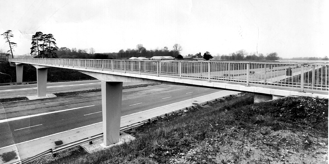
Butler had worked on the Elephant and Castle Shopping Centre and the M1 Calder Bridge while at Gifford and Partners, before joining Faber in 1968. Bond had designed the Windsor End Footbridge for Buckinghamshire County Council, and worked on refurbishment of the suspension system for Marlow Bridge. He had joined Faber by 1969 and then worked for a time in Nigeria before returning to the UK to work on bridge designs for the Hope cement works (this one, and also the subject of my next post). Bond's potted autobiography is a hugely entertaining read, revealing that Bond's engineering career was essentially a mistaken diversion for a man clearly with wider interests to pursue.

It isn't immediately clear why Butler and Bond opted for a stress ribbon design. In his 1977 paper describing the bridge, Butler suggests that appearance was of "paramount" importance in a sensitive landscape, and it is worth bearing in mind that the site was originally much more open in appearance than it is today. The cutting slopes rise around 6 metres above the level of the railway track, and rock is present close to the top of the cutting.

Butler indicates that interference with rail traffic during bridge construction was a further concern. The bridge spans 34m, is 1.8m wide, and is 0.16m thick (increasing to 0.38m thick over a short length towards the abutments). However, during preliminary design the design team considerd both an in-situ ribbon slab and one made of precast segments. The in-situ variant was chosen on cost grounds, but it's hard to see how it can have been less disruptive to the railway!


The superstructure of any stress ribbon bridge is economic in its use of materials (here it is just the deck slab, 12 prestressing cables, and steel parapets). The bridge hangs like a catenary and the cables are employed both to carry tension to the foundations and to pre-compress the deck concrete. The concrete provides the walking surface, protects the cables against corrosion, and ensures the bridge is sufficiently stiff under loads.

Although the bridge deck is economic, the tension loads inherent in the bridge form can result in expensive foundations. The tension is partly resisted by four ground anchors at each end of the bridge, but the designers struggled to provide sufficient restraint in this way, and opted to also install concrete struts which pass down the cutting slope and below the railway. In the final design as built, the struts, in conjunction with the mass of the abutments, are sufficient to resist all dead loads and the ground anchors are only required to resist the effects of live loads.


The in-situ concrete ribbon was constructed on timber formwork supported on scaffolding, with steel beam supports over the railway to minimise disruption. I imagine that very few stress ribbon bridges have been built in this way.

In 2002, the bridge was used as a test site for bridge dynamic measurement. This recorded a first vertical natural frequency of 2.44 Hz, and a modal damping ratio of approximately 0.5%. Vibration was certainly perceptible when I crossed the bridge, especially when I asked a companion to jump up and down. Perhaps this is the reason why signs restrict the bridge to no more than 20 persons at a time, although I doubt it ever encounters that many at one time (Butler's paper mentions a design live load of 6kN/m2, which is clearly far more than 20 persons).

The bridge was very difficult for me to photograph due to tree growth, so I can recommend Geoff Bond's website for photographs taken shortly after construction.


This is not by any means a significant bridge in the context of international stress ribbon bridges. Within the British context, the main reason for taking note is that its very rarity shows how difficult it can be for engineers to find opportunities to depart from the tried-and-tested. It's always nice to find the instances where engineers did indeed escape from the conventional rut.

Further information:

04 September 2020

Derbyshire Bridges: 2. Railway Bridge, Castleton Road, Hope - Update

Many thanks to crisb who commented on my previous post about this bridge, drawing my attention to a number of publications from 1928-29 shedding further light on its history.

The bridge was mentioned on several occasions in the journal Ferro-Concrete: The Review of Reinforced Concrete. I believe this may have been promoted by L. G. Mouchel and Partners as a way of publicising the Hennebique system of reinforced concrete, for which they held the UK license.

The 117ft (35.7m) long bridge was described as having one 54ft (16.5m) central span, and two 21ft (6.4m) side-spans, sized to allow for future widening of the road. As well as being used in production of cement, the local limestone was crushed to form the aggregate for the concrete used in the bridges. Tests were undertaken to demonstrate that sufficient strength would be achieved.

The journal included this picture of the bridge under construction:


An article appeared in Concrete and Constructional Engineering magazine in 1929 on "Reinforced concrete bridges in Derbyshire". This noted the client as Messrs. G. and T. Earle Ltd., the owner of the cement works, and stated the design engineer as being Mouchel's firm. Messrs. F. Mitchell and Sons Ltd. were identified as the contractor.

This article confirmed the key dimensions of the bridge, also reporting that the structure comprises a 7.5" (190mm) thick reinforced slab, carried on 24" x 9" (610mm x 229mm) secondary beams at 4'3" (1.3m) centres, these supported from the main edge beams.

According to Ferro-Concrete, the completed bridges were "of most artistic appearance".