
The viaduct was completed in 1863 as part of the Midland Railway company's Manchester, Buxton, Matlock and Midland Junction Railway. This railway has a long and complex history, which (if so inclined) you are better off reading at Wikipedia than I am repeating in any detail here. Suffice to say that the route connected Derbyshire to Manchester through the hilly terrain of the Peak District, and substantial civil engineering works were required.

It seems a wonder now that there were ever funds available to build a railway through such difficult terrain, necessitating not only major viaducts but a number of substantial tunnels. Perhaps it is worth imagining what the nature of the highways of the time must have been, for this to have been an attractive alternative.
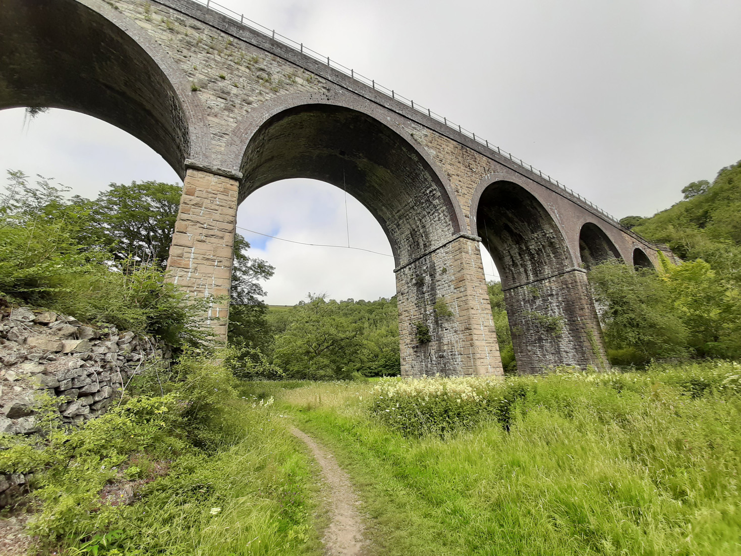
 The viaduct has five arches each spanning 50 feet (15.5m), and is roughly 25m tall. It originally carried two railway tracks, emerging from a tunnel in the steep hillside to the east and then passing along the flank of another hill to the west.
 The railway was closed in 1968, and the route was converted to the Monsal Trail for cyclists and walkers in 1981. The closest you can come now to reliving the steam train experience would be to hurtle westwards on a bicycle at speed from the tunnel mouth into the open air, taking in the views with a sense of astonishment and relief.
 The viaduct design has been credited to William Henry Barlow, perhaps best known for the design of another Midland Railway project, the St Pancras train shed. Headstone Viaduct is far from his most notable bridge: along with John Hawkshaw, he completed Brunel's Clifton Suspension Bridge, and he also designed the replacement for Thomas Bouch's ill-fated Tay Bridge. However, Midland Railway engineer Frederic Campion may have held more direct responsibility.
 The construction of the arch barrels is a little peculiar. The facing voussoirs on each arch comprise seven rings of brickwork (an inner two bonded together, and then five outer rings), down to springing level. The piers and spandrel walls are in rubble stonework, and stone is also used for the lower part of the inner face of the arch barrel. The upper parts of the arch barrel are in brick. It seems an odd arrangement.
Brickwork is also extensively employed above two arches on the south elevation, possibly associated with remedial work completed in 1907-8. I doubt that many visitors notice!
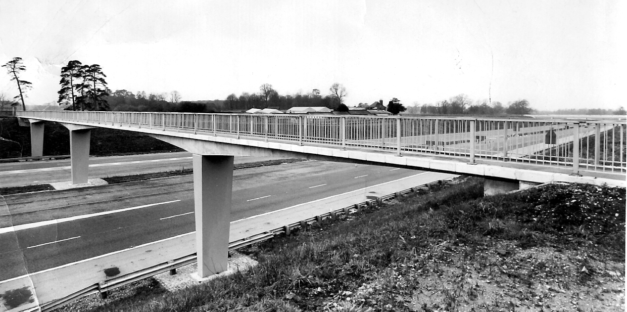
 The overall impression is robust but not excessively so - the scale and nature of the bridge is entirely appropriate to its setting. It's interesting to wonder what would be built if a similarly beautiful valley were to be crossed by a new railway today.
The Victorian polymath and art critic John Ruskin (something of a 19th century Brian Sewell) certainly didn't appreciate either the railway or the viaduct, writing:

As is often the case, age provides architecture not only with grace, but it also elevates the perception of the location as a whole. Without the viaduct, this could just be any other pretty green Pennine dale. The viaduct is the centrepiece, the thing that visitors peering down into the valley from above all point their cameras towards.
 It also provides a fine platform from which to view the surrounding greenery. Many visitors descend the path from the nearby Monsal Head car park to admire the viaduct and the tunnel entrance without going any further. An encounter with England's green and pleasant land need not require a lengthy trek.
 It is certainly worth taking the time to go a little further and follow the path below the viaduct. From above it is impressive, but dwarfed by the surrounding landscape. From below, the opposite is true, it is a stone giant soaring overhead, framing shorter views and guiding the curious visitor eventually to the banks of the River Wye, ultimately responsible for carving this landscape over unimaginable years past.
It has obviously been a site for a more interactive visitor experience in the past. Signs on the viaduct draw attention to metal bars, suspended from the arches and stretched between the stone piers. These are intended to prevent people from leaping off the viaduct attached to a rope and swinging underneath. Certainly nobody was trying it when I visited.
Part of the railway line was reopened as a "heritage" service in 1992. There are broader ambitions to reopen the whole route as a "proper" railway, with Monsal Trail "reprovisioned", whatever that means. Personally, I think it would be a real shame if it denied people the chance to get up close and personal with the trail, its tunnels and viaducts.

Further information:

It seems a wonder now that there were ever funds available to build a railway through such difficult terrain, necessitating not only major viaducts but a number of substantial tunnels. Perhaps it is worth imagining what the nature of the highways of the time must have been, for this to have been an attractive alternative.
 The viaduct has five arches each spanning 50 feet (15.5m), and is roughly 25m tall. It originally carried two railway tracks, emerging from a tunnel in the steep hillside to the east and then passing along the flank of another hill to the west.
 The railway was closed in 1968, and the route was converted to the Monsal Trail for cyclists and walkers in 1981. The closest you can come now to reliving the steam train experience would be to hurtle westwards on a bicycle at speed from the tunnel mouth into the open air, taking in the views with a sense of astonishment and relief.
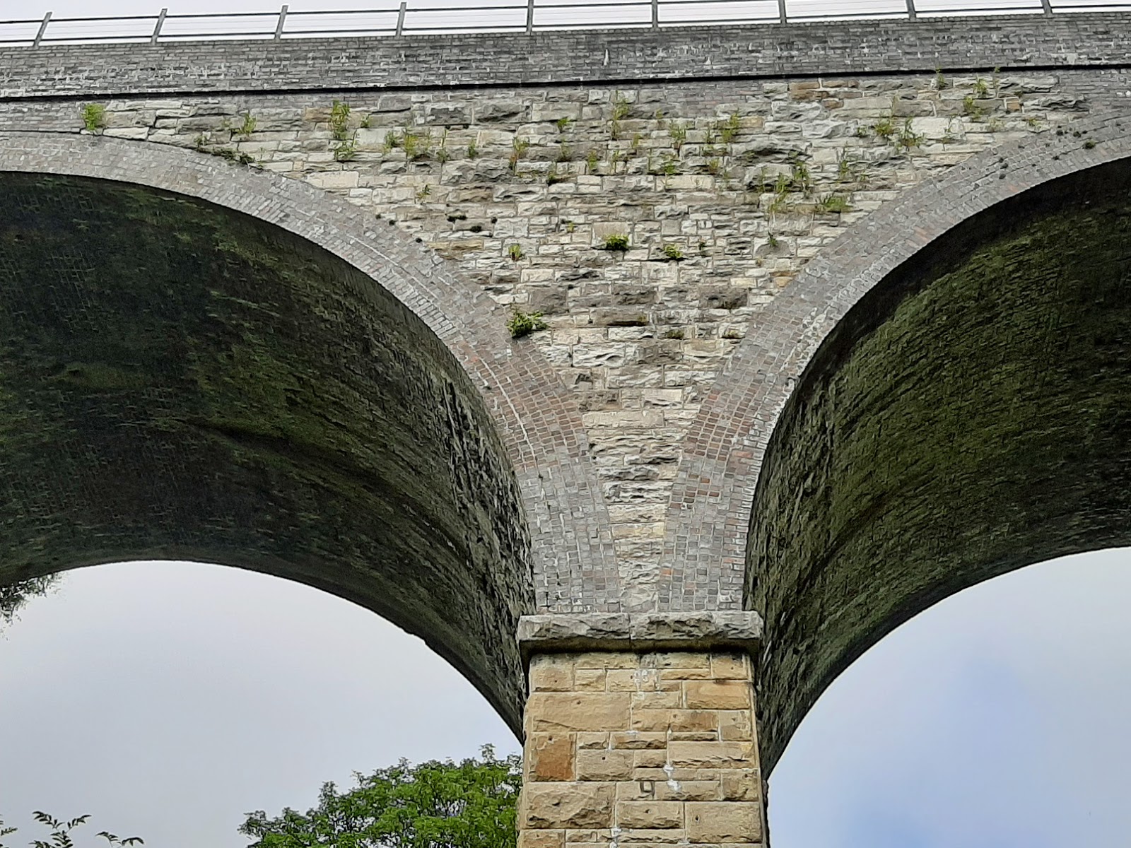 The viaduct design has been credited to William Henry Barlow, perhaps best known for the design of another Midland Railway project, the St Pancras train shed. Headstone Viaduct is far from his most notable bridge: along with John Hawkshaw, he completed Brunel's Clifton Suspension Bridge, and he also designed the replacement for Thomas Bouch's ill-fated Tay Bridge. However, Midland Railway engineer Frederic Campion may have held more direct responsibility.
 The construction of the arch barrels is a little peculiar. The facing voussoirs on each arch comprise seven rings of brickwork (an inner two bonded together, and then five outer rings), down to springing level. The piers and spandrel walls are in rubble stonework, and stone is also used for the lower part of the inner face of the arch barrel. The upper parts of the arch barrel are in brick. It seems an odd arrangement.
Brickwork is also extensively employed above two arches on the south elevation, possibly associated with remedial work completed in 1907-8. I doubt that many visitors notice!
 The overall impression is robust but not excessively so - the scale and nature of the bridge is entirely appropriate to its setting. It's interesting to wonder what would be built if a similarly beautiful valley were to be crossed by a new railway today.
The Victorian polymath and art critic John Ruskin (something of a 19th century Brian Sewell) certainly didn't appreciate either the railway or the viaduct, writing:
"There was a rocky valley between Buxton and Bakewell, once upon a time, divine as the Vale of Tempe ... You Enterprised a Railroad through the valley - you blasted its rocks away, heaped thousands of tons of shale into its lovely stream. The valley is gone, and the Gods with it; and now, every fool in Buxton can be in Bakewell in half an hour, and every fool in Bakewell at Buxton; which you think a lucrative process of exchange – you Fools everywhere."

As is often the case, age provides architecture not only with grace, but it also elevates the perception of the location as a whole. Without the viaduct, this could just be any other pretty green Pennine dale. The viaduct is the centrepiece, the thing that visitors peering down into the valley from above all point their cameras towards.
 It also provides a fine platform from which to view the surrounding greenery. Many visitors descend the path from the nearby Monsal Head car park to admire the viaduct and the tunnel entrance without going any further. An encounter with England's green and pleasant land need not require a lengthy trek.
 It is certainly worth taking the time to go a little further and follow the path below the viaduct. From above it is impressive, but dwarfed by the surrounding landscape. From below, the opposite is true, it is a stone giant soaring overhead, framing shorter views and guiding the curious visitor eventually to the banks of the River Wye, ultimately responsible for carving this landscape over unimaginable years past.
It has obviously been a site for a more interactive visitor experience in the past. Signs on the viaduct draw attention to metal bars, suspended from the arches and stretched between the stone piers. These are intended to prevent people from leaping off the viaduct attached to a rope and swinging underneath. Certainly nobody was trying it when I visited.
Part of the railway line was reopened as a "heritage" service in 1992. There are broader ambitions to reopen the whole route as a "proper" railway, with Monsal Trail "reprovisioned", whatever that means. Personally, I think it would be a real shame if it denied people the chance to get up close and personal with the trail, its tunnels and viaducts.

Further information:
- Google maps
- Wikipedia
- British Listed Buildings
- Engineering Timelines
- Forgotten Relics
- National Transport Trust
- Institution of Civil Engineers Monsal Trail leaflet (PDF)
- An Encyclopaedia of British Bridges (McFetrich, 2019)
- British Railway Bridges and Viaducts (Smith, 1994)


.JPG)
%20artists%20impression.JPG)