Showing posts with label bridge failures. Show all posts

23 June 2019

FIU Bridge Collapse: Designer's analysis

My reader Patrick Sparks has drawn my attention to a presentation from the FIU Bridge designer which makes an interesting read in light of the recent OSHA report.


The linked PDF comprises the minutes of a meeting held to receive a presentation from the bridge designer Figg at 9am on 15th March 2018, just a few hours before the bridge collapsed, plus a series of photos capturing the presentation slides*. Figg were present at a meeting along with the Florida Department of Transportation (FDOT), the contractor MCM, the university FIU and their construction representative BPA. The aim of the meeting was to review cracking which had arisen in the bridge during construction.

(*Is this a normal thing to do in US engineering meetings? It feels very odd to me.)

It is clear that despite the very severe and unexpected cracking which had occurred, nobody present considered it necessary to take any immediate action other than to proceed with re-stressing of the cracked truss diagonal.

The designer "assured that there was no concern with safety of the span suspended over the road". The client's construction adviser specifically asked if the bridge should be propped but the designer stated that it was not necessary.

The actions discussed were mostly take-aways: the construction adviser would review the designer's analysis over the next few days; the designer was working on a scheme to "capture" the cracked truss node; there was agreement that the engineering peer reviewer should take a look at the situation, but no clear action or timescale for them to actually do so.


A re-stressing procedure was due to take place within a few hours following the meeting, but the designer left site rather than stay to observe, and the client's construction representative had not received details of the procedure prior to the meeting.

Reading the notes from the meeting what strikes me is a total lack of clarity from everyone present. Some actions are implied, but none are clearly recorded. Nobody was present who could provide meaningful comment or review of what the designer had to say. Those present accepted that there was a serious and unexplained issue, but felt it appropriate to push on with re-stressing the truss end diagonal even through the cause of the cracks was completely unknown. There is no sense in the minutes of a forensic approach to the failure.

Some of this is not unexpected - I have sat in similar meetings where there is no clear leadership and the approach to solving a problem appears to be unstructured. It is, however, something for other projects to learn from.

There are inconsistencies between what the designer presented, and what the OSHA investigation reports.


The first of these relates to the stage when the falsework supporting the concrete truss was removed, leaving it sitting on temporary supports before transport to the bridge site. The designer's presentation states there were no significant cracks at this time, but the OSHA report reveals that a cracking or popping sound was heard and several cracks were then visible in exactly the same part of the structure that led to later concern.

Much of the presentation is given over to a re-calculation of vertical transverse bending in the end diaphragms of the bridge. It isn't clear why, as the visible cracks were not characteristic of vertical bending.

A key part of the designer's re-analysis starts on page 27 of the PDF, headed "Total Nodal Shear Stability". This is their check of whether the truss end node can fail by punching out of the end diaphragm. Differences to the OSHA analysis are readily apparent: OSHA calculated shear on a horizontal plane in line with a casting joint, while the designer considered shear on two vertical planes through the diaphragm either side of the node.


OSHA's calculations show the horizontal plane to have had insufficient strength: the concrete area was relatively small, the construction joint was a plane of weakness, the area of reinforcing bar passing through the plane appears to have been small. The designer's calculations showed the vertical plane(s) to be ok: the concrete area was relatively large and doubled (two shear planes either side of the truss diagonal), the area of reinforcement was large, and transverse prestress provided a "clamping" force which enhanced shear strength.

The discrepancy indicates that the designer did not re-calculate shear on the horizontal plane, which was later found to form part of the observed failure mechanism. Both shear planes should have been checked (and any others which might be identified as being potentially weaker).

The designer considered in detail the changes in support of the truss from the initial temporary supports to the permanent supports, with a different shim arrangement, and concluded that it was unclear how this change could possibly create the cracks that were observed. The cracks were described by the designer as "spalls", seemingly not recognising that the end node was in fact in the process of gradually moving and becoming detached from the body of concrete.

The designer's conclusion was as follows:


Paraphrasing this, their calculations showed that the bridge was okay, therefore the bridge was okay. The cracks could not be significant if the computer model did not explain them.

In hindsight, this sounds obviously faulty reasoning, but we should be wary of hindsight bias. With the evidence clearly laid out before us, the significance of the cracks may now seem obvious. However, with the cracks unexplained, the designer was using their familiar tools to try and understand what had happened. Although OSHA has been quick to blame everybody involved in the project for their alleged failures, I think there will be many designers who will wonder whether they would have done any different.

Another cognitive bias may have applied back in March 2018. Here's what Wikipedia has to say about confirmation bias:
Confirmation biases contribute to overconfidence in personal beliefs and can maintain or strengthen beliefs in the face of contrary evidence.
Is this what happened? Were project participants willing to ignore the evidence of progressive failure because it simply did not fit in with their mental model of how the structure should behave? The designer is likely to have had considerable experience of computer modelling, and of structures that behave in a manner that doesn't contradict it. It's easy in that situation to think that the computer modelling is right (in fact, errors and omissions may be made in computer modelling from time to time, but usually structures behave well enough for this not to become evident).

Groupthink may also have had an influence on the outcome. Here is Wikipedia again:
Group members try to minimise conflict and reach a consensus decision without critical evaluation of alternative viewpoints ...
The minutes of the project meeting show that the designer's viewpoint was challenged, but it seems that challenge wasn't pursued with sufficient firmness - the designer's recommendations (to re-stress the truss diagonal, and not to prop the structure) were followed without giving time for alternative views to inform these decisions. The minutes are unclear who was responsible for the decision anyway: the word "safety" appears only once in the minutes, and it is not clear from the record who took the lead responsibility for safety of the actions taken.

Everyone is vulnerable to confirmation bias, groupthink and similar irrational judgements. The evidence is that cognitive biases in general have a big impact on how individuals and groups operate in many widely varying contexts. Recognition of this has driven the entire field of behavioural economics, but it's not something you hear much about in the engineering context.

I hope that the official incident investigation digs into some of these issues, as I think they are in many ways of wider relevance than issues of calculations and concrete strength, the specifics of which will always vary from project to project. It would be foolish for designers of steel bridges to think that the FIU bridge incident is not relevant to them, for example. The factors (including, often, commercial pressures) which lead to poor analysis of evidence and hence poor decision-making cut across all types of project and many types of error.

I feel the issue of identifying effective behaviours and putting in place processes and a culture which encourage rather than discourage them is the key area where attention should be focused.

20 June 2019

FIU Bridge collapse: OSHA investigation findings


A report has been published regarding the collapse of the FIU Pedestrian Bridge. The bridge collapsed on 15th March last year during construction, resulting in six fatalities and several serious injuries.

The report has been prepared by the US Occupational Health and Safety Administration (OSHA), which I take to be roughly equivalent to the UK's Health and Safety Executive (HSE). A thorough investigation is being carried out by the US National Transportation Safety Board (NTSB), due to be completed later this year, but the OSHA report largely echoes preliminary findings issued by NTSB last November.

There is no direct equivalent to the NTSB in the UK: we have national bodies for investigating aviation and railway accidents, but not for highways, a gap that is long overdue for filling (no doubt, we will have to wait for our own serious incident for this to change, rather than learning from elsewhere).

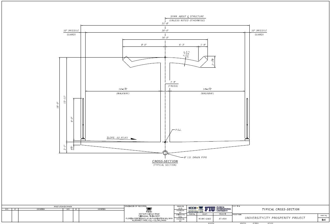
The bridge was a highly unusual design, comprising two concrete truss spans, each with a single truss along the centre-line of the bridge deck. A pylon and steel pipe stays above the trusses were arranged to give the impression of a cable-stayed bridge, but were largely decorative, with the only reported structural purpose being to reduce pedestrian-induced vibration in the main structural elements. I discussed the design in more detail in March 2018.

OSHA's report into what went wrong appears detailed and thorough, but some caveats are in order.

The report does not hesitate to apportion blame, stating that the designer (Figg), design peer reviewer (Louis Berger, performing an independent check of the entire design), the construction engineer and inspector (BPA, acting as FIU's representative), and the contractor (Munilla Construction Management, MCM) all failed in their duties and missed opportunities to prevent the collapse.

Oddly, less blame is attributed by OSHA to the highway authority who allowed the bridge to be built above live traffic (Florida Department of Transportation, FDOT). I've commented on this previously: in the UK and in some other jurisdictions, a highway authority would undertake a process of technical approval for any new bridge built over or under their infrastructure, to protect their own interests which include both avoiding undue impact on traffic, and protecting the safety of highway users.

FDOT took some interest in the project, having their in-house structural engineering group review the designs, and they were represented at regular site meetings including a fateful meeting on the morning of the collapse. Like all the other participants, FDOT's representative missed the opportunity to call a halt to activity on site, but oddly, this is omitted from the report’s executive summary. It is also left unclear whether FDOT were aware of or agreed to gaps in the scope of the independent peer reviewer, who reportedly did not check the bridge in any construction stages, only in its final state.

OSHA appear to have had extensive access to evidence from before and after the bridge collapse, but their report shows only limited sign of having talked to the main participants. Allegations are made, but any responses received are absent. Figg have rapidly gone on record to criticise the report, stating that they are prevented from saying more publicly while the NTSB investigation continues.

So take anything that follows with a pinch of salt – despite the report's impression of thoroughness, it may be partial and unfair. We'll have to wait until later this year to see what the NTSB have to say.

OSHA start by repeatedly drawing attention to the fact that the bridge was expected to be an aesthetically attractive landmark structure. No connection to the collapse is made explicit, but they seem to want to create the impression that the circumstances of procurement contributed to failure. Otherwise, why mention the topic? Personally, I think the FIU were entitled to rely upon the professional integrity and judgement of their various advisers and contractors, and cannot be blamed for wanting a nice bridge.

The main truss span was cast off-site in four stages on a falsework assembly, before being picked up by a self-propelled modular transporter (SPMT), driven to site, and then set down on its final supports.


Prior to the SPMT stage, all truss members which would experience tension either during construction or in service were prestressed using stressing bars. Most stressing bars were grouted in, except for the two end diagonals (truss members 2 and 11), as these required prestress to be adjusted during construction.

The first sign of trouble came when the temporary falsework was removed, leaving the truss span supported on temporary trestles at each end. Operatives reported hearing a "loud popping sound", and soon discovered cracks at the bases of diagonals 2 and 11, where they connect to the bridge's lower deck slab. In this configuration, the end diagonals were in compression, so any prestress applied should have been minimal. Photographs of the cracks were shared with the designer, who OSHA state showed no real concern. The image on the right shows one of the larger cracks at this stage, at the bottom of diagonal 11.

Over a week later, the structure was transferred from the temporary end supports onto the SPMT ready for transport to site. The SPMT carried the bridge on the lower truss nodes one bay in from the end supports. At this stage, diagonals 2 and 11 would have been in tension, and prestressing would have been required. Once placed on the permanent supports, the intention was then to de-stress the bars in these members.


According to the OSHA report, no further cracks appeared and the initial cracks did not develop further during transportation and installation of the truss span. Member 2 was then de-stressed without incident, but further signs of trouble emerged rapidly during de-stressing of member 11. Multiple cracks appeared at the lower node of this member, leading one prestressing operative to report that "it cracked like hell".

Two days later, pictures of the cracks were sent to the designer for comment. Construction operatives later stated that the cracks had already grown larger, and photographs taken at this stage appear quite alarming in what they show, with evidence that the truss node was separating from the lower slab. Nonetheless, the designer stated that "this is not a safety issue", proposing that member 11 be re-stressed to return it to its previous state. The designer did not plan to attend site during this operation.

Photographs of the cracks taken over the next two days look steadily more alarming. A key meeting was held 5 days after installation, attended by FIU, the designer, contractor, construction inspector, and FDOT. The designer had now inspected the cracks (which continued to grow) in person, but stated that there was still no safety concern.

Nonetheless, they emphasised the need to proceed with construction of the second span (which, when made continuous with the first span, would reduce loads on member 11), and stated that they would examine methods by which the progressively cracking node could be "captured" or "restrained". According to OSHA, no reference was made back to the peer reviewer at any stage.


On the face of it, the recommendation to re-stress diagonal 11 was very strange. The stressing bars were provided for the temporary condition when the bridge was supported on an SPMT, a situation which no longer existed. Once the bridge was erected on the permanent supports, re-stressing the diagonal added to load in the diagonal and its connecting nodes, rather than reducing it.

Re-stressing commenced as instructed, and was nearly complete when the bridge collapsed.

OSHA describe the failure as a "concrete blow-out", but an appropriate term for it is a shear or punching shear failure: the upper part of the truss node sheared clear out of the lower deck slab, partially along the lines of construction joints created during the original phased construction pour.

The image below shows the node after failure, looking towards the end of the deck. The large empty pocket was originally solid concrete; the rough area in the centre of the bottom edge of the photo was originally where the truss diagonal connected into the deck. The various vertical ducts appear to be for lighting cables or similar.


The next photo shows the same area looking straight onto the end face of the deck slab after it was removed from the collapse site. The empty pocket at the top is the same empty pocket visible in the previous image.


The cracks observed prior to failure are consistent with this, including longitudinal splitting seen on diagonal 11, which was presumably caused by the longitudinal movement of the bottom node, splitting occurring due to the different anchoring positions of the upper and lower stressing bars within the concrete.

With the node destroyed, the truss was no longer fully triangulated at all points, and the full load of the bridge could only be carried by bending of the top or bottom truss members (the roof canopy and the deck slab), a condition which neither member could ever have been designed for. This is precisely what is meant when the design is described as lacking redundancy – there was no secondary load path. In addition, there was limited ductility – shear failure can occur much more suddenly than a bending failure.

Here is the node detail as shown in the OSHA report, viewed from the side – the position of the construction joint is not clear but the report states elsewhere that the truss diagonals and verticals were cast after the deck slab, so the joint runs horizontally somewhere through the middle of the diagram.

OSHA's calculations show that the combined capacity of reinforcing bars crossing the construction joint, plus friction caused by the vertical component of axial load in diagonal 11, were insufficient (in accordance with the design codes) to resist the horizontal component of axial load in diagonal 11: the shear demand was calculated to be 22% higher than the shear capacity. Re-stressing the bars made the situation worse, with demand then 45% higher than capacity. I have some diagrams below which perhaps make this clearer.

The potential punching shear failure is shown in this diagram in the OSHA report, viewing the node from above with the force from member 11 acting towards the bottom of the diagram:


The report doesn't spell out why failure did not occur when the truss was first landed on its permanent supports: the loads and prestress state at this time were the same as immediately prior to the actual failure.

The progressive nature of the cracking may be relevant here: the re-stressing was applied to a structure which had already severely fractured, showing evidence of slip along the shear planes of the construction joints. In this situation, resistance would have been greatly reduced below what the design code suggests. The fracturing and slip itself may have been caused by an initial failure of the concrete surface upon installation, with the progressive cracking then caused by plastic deformation of the reinforcing bars passing across the joint.

The visible evidence of the punching shear failure also indicates the failure to have been 3-dimensional and the 2-d drawing of the node is therefore misleading. What particularly bothers me about the node detail is that it is highly unclear how the compression in diagonal 11 is transferred into the tension system of the post-tensioned bridge deck. The OSHA report draws attention to this, and it seems to be the case that a lack of adequate provision to transfer these forces laterally from the plane of the truss into the plane of the deck contributed to the failure.

In the OSHA analysis, the truss node was therefore under-designed for the loads it had to carry; it had not been checked in this condition by the independent checker (who reportedly considered only the final situation once the two spans were made continuous); and there was no redundancy in the design, such that if any one truss member failed, bridge collapse was inevitable. To add to the bridge's vulnerability, vertical ducts were located either side of the node, potentially weakening the whole area – these are visible in one of the photographs included above.

It may be partial at this stage, but the picture that OSHA sets out is consistent and compelling.

Their report is lacking in diagrams which clearly show the lines of force, the positions of the cracks, and the eventual failure, so I've had a go.


The first diagram shows the compression in diagonal 11 (red), which can be resolved into a vertical compression force and a horizontal shear force where the diagonal connects to the deck (both in grey), with the horizontal force balanced by tension in the deck (blue).


The second diagram shows the position of cracks visible prior to failure (yellow), and the direction of movement of the upper part of the node corresponding to these cracks (white).


The final diagram shows very roughly the planes along which the concrete failed to cause collapse. On the left hand edge of the section highlighted in black, a block of concrete punched clean out, while on the right hand edge of the same area, failure was in pure shear through a construction joint between the diagonal and the deck.

Note that the construction drawing shows shear reinforcement passing through that part of the construction joint – failed reinforcement can be seen in some of the OSHA photographs. The report doesn't state the diameter of these bars, but from the photographs they appear to be very small compared to other visible reinforcement.

OSHA concludes (a) that the truss node was under-designed for the forces it had to carry, and (b) that a series of competent professionals failed to take adequate precautions when clear evidence of problems with the structure came to light. OSHA addresses the "what", but not the "why".

I think speculation should be limited and those involved should have the opportunity to explain their actions and identify any flaws in OSHA's argument. However, I think there are a number of questions which should be asked:
  1. How did the agency responsible for highway safety ensure that an acceptable process was in place for design and construction, and did they review or agree any of the methods of design to be used, especially for critical or unusual details? In the UK, the design methodology would be presented in advance through a Technical Approval process, reviewed and accepted by the relevant infrastructure authority. This process was introduced into the industry following notorious bridge failures in the 1970s. Do the US authorities apply anything similar, and if not, is there a failure to learn from international experience?
  2. Who determined and who accepted the peer reviewer's scope? This was an unusual design, with significant changes in load at different construction stages, yet apparently the peer reviewer entirely ignored key construction stages, including the stage where collapse occurred. Why was this not part of their scope?
  3. What calculations did the designer undertake? Were key calculations missed, or incorrect, and if so, what errors were made? The OSHA report presents the conclusions of the agency's own calculations but says nothing about what the designer actually did or why in their view the node design was adequate.
  4. Given the structure's clear lack of redundancy, how did the designer conceptualise critical details? Were simple shear rules applied or were complex details such as the node modelled in more detail? I would have expected a finite element model of a detail like this, unless simple calculations showed it to be highly robust.
  5. Why did the designer state that the cracking was not a safety issue? With hindsight, it seems clear that a serious developing failure should have been apparent, with the cracking demonstrating insufficient strength. It should also have been clear that once the concrete cracked in the manner it did, the strength of the node was immediately reduced.
  6. Was it reasonable for the other project participants to rely entirely on the designer's advice? OSHA's view is that they did not act reasonably – that they had sufficient expertise to stop work until further precautions were in place. I'm far from convinced about that: the designer was clearly the structural engineering expert and from one perspective it's hardly unexpected for others to defer to that.
  7. What external pressures existed, relating to cost or programme, or to a desire not to disrupt traffic further?
  8. Was this the most appropriate design, particularly with the choice of materials? It seems difficult to believe that this failure would have occurred in a steel truss design.
OSHA's report is very direct and reductive in its analysis of failure. The truss node failed in punching shear. The designed capacity of the node to resist this failure mode was inadequate. The designer, and everyone else involved in the project, failed to recognise the seriousness of the initial cracking. Nobody took any steps to prevent the cracking from progressing, or to safeguard highway traffic. The action taken, re-stressing the prestress bars, made things worse rather than better.

This is a clear causal chain, and in the Swiss cheese model of systemic failure, all the holes in the various layers of cheese lined up. However, I'm not convinced that it is sufficient simply to identify human error: mistakes are inevitable, and those responsible for the system should put in place mechanisms both to identify error (such as independent checking), and to minimise its impacts (such as adoption of robust materials and structural forms).

If the OSHA report is accurate, then serious issues are apparent, and from conversations with others in the industry, these issues are not unique to the FIU pedestrian bridge project. Some of the key issues appear to be behavioural: reliance on advice without challenge; the assumption that competent people do everything right; a reluctance to take the evidence of today and imagine what it will result in tomorrow; the suggestion that because an occurrence is not yet explained, no action should be taken.

Many of these can be attributed to cognitive biases and even if they were found not to have caused the failure of the FIU bridge, those involved in other projects should still reflect on their own safety culture, the way in which teams respond when challenged, and what can be done to ensure appropriate behaviours are rewarded rather than discouraged. Engineers should also reflect on whether the divisions of responsibility in their technical governance and assurance processes are fit for purpose. Given that errors will occur on some project at some time, what are we doing to prevent them resulting in catastrophic outcomes?

My experience is that structural engineers are often prone to simply following normal process, standards and methods. Risk assessment too often concentrates on construction and operational hazards or even just on commercial risks. It is rare to see a structural engineering plan of work arising directly from a meaningful analysis of the risks of structural failure: often, it's just assumed that codes and standards are sufficient to address those particular risks. The best way to work out how to make a structure stand up is first to work out how it would fall down, a lesson that could have been learned from many disasters but is still not embedded properly in regular practice.

15 August 2018

Collapse of the Polcevera Viaduct


I'm sure most of my readers will have seen yesterday's tragic news that the Polcevera Viaduct in Genoa, Italy, collapsed, with at least 39 fatalities reported. At the time of writing, rescue and recovery efforts are ongoing. A state of emergency has been declared in the local region.

The 1.1km long viaduct carried a major toll road through Genoa, and was a key connection in the route from central and southern Italy to the south coast of France. It was completed in 1967 to a design by the famous Italian engineer Riccardo Morandi, one of a series of innovative concrete stayed bridges that he created starting with the Lake Maracaibo bridge in 1962.

These were distinguished by the use of very simple stay arrangements, using prestressed concrete stays rather than the steel cables already in wide use at the time (e.g. Strömsund Bridge in Sweden, 1955, and the Nordbrücke in Düsseldorf, 1957).


Eduardo Torroja's Tempul Aqueduct, built in 1926, is one of the few predecessors, although Torroja used concrete only as a protective material, it was not prestressed. Concrete-encased stays were also later used on the Prins Willem-Alexanderbrug in the Netherlands (1972) and the Metten Danube Bridge (1981). Morandi's tower arrangement was also used (without the concrete stays) on the Chaco Corrientes Bridge in Argentina (1973).

For more on Morandi's bridges and their relatives, see Walter Podolny's 1973 paper Cable-stayed Bridges of Prestressed Concrete.

Morandi's designs, although highly innovative, were a dead end. They required extensive temporary works to support the bridge deck until the stays were completed.

At Polcevera, temporary prestressing was used in the cantilevering deck sections, only to be removed once the stays had been installed. For his bridge at Wadi el Kuf, in Libya (1972), an array of temporary stay cables was used to support the longer spans, with all these cables then removed, rather than left in place as the permanent support system, which was the more logical and much more widespread solution. The Libyan bridge, incidentally, was recently closed for safety reasons.


Possibly relevant to the Genoa disaster, these designs also lack structural redundancy. The failure of any one key structural member of the bridge can lead to disproportionate collapse.

The Polcevera Viaduct, and its cousins, have been much admired by engineers and architects.

Michel Virlogeux, in his paper Bridges with Multiple Cable-stayed Spans, notes that the Lake Maracaibo Bridge was "much admired by architects who understand the evident flow of forces and who are sensitive to the impression of strength that emanates from the mass and shapes of the structure". Leonardo Fernandez Troyano described the same structure as "one of the great works in the recent history of bridges" in his book Bridge Engineering - A Global Perspective. In a 2010 paper summarising Morandi's work, Luca Sampo claimed that the Polcevera bridge's "technical features may still today be considered unsurpassed".

There is plenty of speculation on the internet regarding the cause of the collapse, which I won't repeat here.

The bridge's brand-new Wikipedia article is a pretty good source of information. There's a paper from 1995 which discusses previous remedial works to the bridge's main stays. Probably the best read is a contemporary article from 1968 with lots of construction drawings and photographs. All the images I've used here are taken from that article.

08 April 2018

Five unanswered questions on the FIU pedestrian bridge collapse

The flood of news that followed the collapse of the FIU Bridge in Miami on 15th March has slowed to a trickle.

The US National Transportation Safety Board (NTSB) have been crawling all over the bridge wreckage (see videos below). It has been reported that they have asked project participants not to share anything with the media. Their preliminary report should be published this month.


A couple of stories note that the project was running over budget and behind programme, caused in part by design changes instigated by Florida Department of Transportation (FDOT). Is this relevant? It is hard to tell. Design-and-build projects often proceed to a difficult programme, never with a positive impact on quality and safety, but most are, of course, built safely.


Anonymous Canadian YouTuber AvE is said to have found the "smoking gun", and offers up a useful analysis of some of the evidence publicly available (I've embedded the video further down this post). His explanation suggests that stressing rods in truss member 11 (see diagram above, taken from the preliminary design drawings) were over-tightened, causing the rods to fail suddenly - but this was a compression member at the time of collapse, and the rods in it should not have been relevant to its load capacity.

Engineers have pointed to the lack of structural redundancy in the design, with its single truss carrying all the load. Catastrophic failure of any individual truss member would therefore inevitably result in collapse of the bridge. However, there's nothing wrong with "fracture-critical" design so long as members (and their connections) are designed to be invulnerable to fracture.

The most comprehensive discussion of the failure that I've seen can be found on the eng-tips forum, currently extending over five separate discussion threads: 1, 2, 3, 4, 5. Be prepared to give up several hours if you want to dive into those in any serious depth.

I think the cause of the collapse will be found to be multi-dimensional. There must be an immediate physical cause of failure: the structure was not adequate for the loads applied to it (at the time of collapse, the only loads of significance were self-weight and prestress). That may relate to defects in construction and/or design, and it may relate to failures of process (doing the wrong thing). That in turn may have been caused by human failures: miscommunication, or plain irresponsibility. Behind this, there will be a wider context of budget, programme, regulatory, political, commercial factors and the like. Some of this is captured in Alfred Pugsley's enduring phrase, the "engineering climatology", the cultural environment within which engineers operate.

I have some questions I would want answered before hazarding a clear speculation as to what happened, and why.

1. Who was responsible for what?
FDOT have used every opportunity to disassociate themselves from the bridge failure, issuing press releases to make clear that their role was only budgetary (channelling funding), or administrative (monitoring progress in use of funding). FDOT are clear that FIU, the contractor MCM and the designer Figg were entirely responsible for the safety of the structure and its construction.

But this is not clear at all.

FDOT have acknowledged that part of their role was to "authorize utilization of aerial space above the state road". They also attended meetings with the design-build team, including one just a few hours prior to the collapse to review cracks found in the concrete. Their representative at that meeting was an engineer, not an accountant.

It seems to me that the designer, Figg, was responsible for the safety of their design, and any amendments made to the design that they had knowledge of. The contractor, MCM, was responsible for following the design and any standard specifications. Both clearly have a duty to the public to ensure the works are safe.

However, FDOT also have a duty to the public. If they had any reason to suspect the works were not safe, presumably they would not have authorised use of the space above the road.

In the United Kingdom, they would have considered the competence (and available insurance) of the project participants. They would also have reviewed the technical proposals for the design to ensure they were appropriate and in line with good practice, and they would have accepted a certificate from the designer confirming the design had been prepared in accordance with what had been agreed. They may also accept a certificate from the contractor confirming the structure had been built in accordance with the approved design. In the UK, they would have required the appointment of an independent design checker, with further check certification.

A particularly prudent public authority might also consider that before reopening a road to traffic passing below a partially complete structure, they might seek specific assurances regarding the safety of the structure in its interim state, to confirm that the design covered the state the structure was being left in temporarily, and to confirm that the construction completed to that point was compliant.

I don't think FDOT can have expected anything to go wrong. The question, however, is whether their technical assurance procedures were sufficient for them to reasonably judge that it was safe to open the road below an incomplete bridge. A "hands-off" approach is clearly a nonsense, otherwise they would be obliged to let all kinds of dangerous work take place without regard to highway safety. The highway authority should, in my view, only be relying on the word of the design-build team if they have a process in place to ensure that word is trustworthy.

2. Why prestressed concrete?

This really does need explaining. Concrete truss bridges are pretty rare, and those that do exist are generally historic.

The reasons for this are not primarily safety-related. A steel truss will be lighter than a concrete truss, making foundations and temporary works less expensive. Parts can be largely prefabricated and assembled, rather than requiring complex cast in-situ works. Temporary construction arrangements are made easier due to the material's better ability to deal with reversal of load.

In some countries, steel will be preferred because there are fewer hidden critical details, a nervousness born out of a past history of failures in post-tensioned bridges when hidden prestressing tendons corrode. That is presumably less of an issue in a warm-weather climate such as Florida.

The positive side-benefit of selecting steel is that it is not normally prone to sudden, brittle failure. It will tolerate overstress by undergoing plastic deformation; yielding and sagging, and giving forewarning before failure.

The same is not true of prestressed concrete, and especially where it is subject to high shear stresses. Failure of a prestressing tendon can be sudden and explosive. Both compressive and shear failure of concrete can be sudden, with little prior warning, especially if there is a lack of conventional reinforcement.

Photographs of the FIU bridge do not reveal large quantities of conventional reinforcement, indeed they seem to show the opposite. The bridge may therefore have been highly dependent on the integrity of the prestressing rods for its load capacity. The interaction of forces at the truss nodes will have been especially complex, given the proximity of the prestress anchorages to these nodes.

With all this in mind, the choice of prestressed concrete seems likely to have contributed to the suddenness of the bridge collapse. So: why was prestressed concrete chosen?

3. What was the nature and location of the reported crack?
It's known that there was a crack at the north end of the bridge, the end which failed. The project's design engineer had phoned FDOT in the days before collapse to report the crack. FDOT had joined the project team for a site meeting to discuss the crack on the morning just a couple of hours before the bridge collapsed.

After the meeting, work was undertaken on the bridge to adjust prestressing rods. It's not entirely clear whether this work was intended to address the cracking, although a link is clearly possible.

It's not clear at this stage whether the crack is actually relevant. It is evidence of a problem, but not necessarily the same problem as was being dealt with at the time of collapse, and not necessarily the same problem which caused failure.

4. Why was work being undertaken on the stressing system immediately prior to collapse, what was this work, and who instructed it?
According to the NTSB:
The investigative team has confirmed that workers were adjusting tension on the two tensioning rods located in the diagonal member at the north end of the span when the bridge collapsed. They had done this same work earlier at the south end, moved to the north side, and had adjusted one rod. They were working on the second rod when the span failed and collapsed.  The roadway was not closed while this work was being performed.
This refers to member 11. Attentive readers will note from the truss diagram above that member 11 was shown (in the preliminary design) with no prestressing. In the permanent load case, it does not require prestressing, as it is under compression under all permanent and imposed loads. However, the design was evidently changed to suit the construction arrangement, which required the span to sit temporarily on a self-propelled modular transporter during installation, supported at the truss node below members 9 and 10. The end part of the truss cantilevered beyond this during transportation, which will have induced tension in member 11.

The prestressing bars in member 11 were therefore required only as a temporary measure during transportation. You would expect them to have been de-stressed (and possibly removed) once the bridge was sat on its permanent supports.

Indeed, that's precisely what a construction representative appeared to say would happen in the "smoking gun" video (starting at 8 minutes in):


There is an obvious discrepancy here. It makes sense that rods in member 11 would be de-tensioned before traffic was allowed back under the bridge, simply because it was convenient to do so while the highway remained a construction site. It does not make sense that any further adjustments were required afterwards; that implies that the bars had not been de-stressed at the intended time.

As well as knowing what was done, a key question is who instructed it, who agreed to it, and why they considered it to be a safe operation to perform above live traffic. There can have been no consideration that the de-stressing work could endanger the bridge.

5. Why was the end truss diagonal (member 11) insufficiently robust to accommodate whatever change in load effect occurred during the re-stressing operation?

Indeed simple calculations should show that the adjustment of stress in member 11 should have been minimal: the compression due to the bridge's self-weight should have been far greater than any stress induced by the prestressing rods. Follow the earlier link to the eng-tips forum for calculations which set this out.

Even in a temporary condition, where reduced factors of safety are sometimes accepted, the concrete truss member and its end nodes should have been robust enough to accommodate any small variations in load caused during construction operations. This should be true even for unexpected changes in load.

The prestress in the stressing bars was being adjusted by means of a hydraulic jack. According to the NTSB statement, one of the two bars had been adjusted, and the second was being worked on when the bridge failed. This will have created an eccentric load effect in member 11, but I doubt that on its own is sufficient to cause failure, and it can be checked beforehand.

There are other issues with hydraulic jacking: in order to loosen the nuts securing the stressing rod, a greater prestress has to be applied initially to allow the nut to be freed. There are risks of hydraulic failure in the jack. The possibility of some sort of failure in the jack, the rod, or the rod anchors, could result in a dynamic shock load being applied to the concrete, but it should have been designed to be robust enough to accommodate any foreseeable range of loading, especially considering that member 11 would be required to carry significantly greater loads once the bridge opened to the public.

I've read a lot of speculation about whether member 11 failed at its upper or lower end, or along its length. There isn't yet sufficient evidence available to do more than speculate. However, the general question remains: why was this part of the bridge not sufficiently robust? This is not a question about the load, or about material defects, it's a question about general good practice in design and detailing, especially for one critical member and two critical nodes on which the entire capacity of the bridge depended.

17 March 2018

The collapse of the FIU Sweetwater Pedestrian Bridge

I am reluctant to add to the media blizzard surrounding the tragic collapse of the Florida International University (FIU) pedestrian bridge in Miami. As I am typing this, the recovery operation is not yet complete, and I think it is both difficult and inappropriate to speculate in too much detail on why the bridge failed with such awful consequences.

I will therefore try to be cautious and factual in what I say, as it seems clear that the reasons for the bridge collapse will be better identified and shared by those with full access to the facts. The desire to rapidly identify causation (and to lay blame) is understandable, but I would like to minimise speculation.

Media coverage
Much of the coverage in the press has been ill-informed guesswork, attempting to draw together whatever half-truths have emerged in order to flag issues which may or may not ultimately prove to be meaningful.

Prime suspects identified by the media include past failures attributed to the two main design-and-build companies involved in the FIU bridge project, MCM (the contractor) and Figg (the designer). Repeated quality failings are a possible issue, but my experience is that there are almost always many contributing causes to any serious failure.

There are even less likely culprits put forward on Twitter: Trump (of course), a false-flag conspiracy, immigrant labour, and most egregiously of all, "diversity-hiring". For the sake of our sanity (often difficult when reading Twitter), I'll say nothing more about these and return to the suspects fingered in the mainstream media.

"Innovation" is linked by one engineering professor to "unexpected failure", as if to imply that innovation is always too risky an approach to take. He may have been misquoted, but this criticism is repeated elsewhere, giving the impression that 'doing new stuff' is so dangerous that it should never be attempted. Says the prof: "Innovations always bring potential 'failure modes' that have not been previously experienced".

There's no doubt that innovation can introduce new risks, but these are normally managed through appropriate review and risk management. I've seen nothing to suggest that the designer, checker, contractor, highway authority (Florida Department of Transportation, FDOT), or owner's engineer (TY Lin) had any doubt about the safety of any of this bridge's innovations in advance. In any event, it is clear from TY Lin's project specification that innovation was something their client would evaluate positively: they actively sought it out.

What innovation is at issue anyway? Many of the news reports point the finger at Accelerated Bridge Construction (ABC), the method adopted by the contractor to install the bridge span across a busy highway with as little disruption to traffic as possible. Ironically, ABC is something that FIU have a keen interest in, and in promoting their bid to build the bridge, the MCM-Figg team enthusiastically drew attention to the connection.

ABC refers to a family of methods for building bridges faster, usually more safely, and often cheaper. The common elements are the use of offsite or modular pre-construction techniques, so that bridges are assembled in-situ as quickly as possible, rather than built entirely in place. Engineers promoting ABC techniques in the US have come up with some excellent ideas, but it isn't fundamentally anything special, and rapid-installation techniques are widely used around the world. For a bridge such as the FIU Pedestrian Bridge, spanning a busy highway, you'd have to be asking serious questions of anyone who didn't adopt an ABC approach. Again, FIU's project specification made clear that ABC techniques would be acceptable, setting out associated construction requirements.

The span which collapsed was the first of two spans due to be installed, and is a simply supported concrete truss bridge designed to sit on its end-supports without any further temporary support (or indeed, permanent support - more on that later). It was built nearby and then wheeled into place on self-propelled modular transporters (SPMTs), an increasingly common way to build a bridge. In addition to reduced traffic disruption, a key driver for this was the presence of overhead power lines at one end of the bridge, which made craneage a less attractive approach. You can see the power lines at the left hand edge of a general arrangement drawing shared on Twitter:

Accelerated bridge construction is cited often in the initial news coverage of this disaster, but it is not in itself relevant, given that the bridge span was designed to span between its piers in both the temporary and permanent cases. More on this below.

Another 'issue' cited often in coverage is simply why the span was allowed to remain in place above live traffic. The highway authority, FDOT, have been at pains to rapidly disassociate themselves from the project, but have stated that it was their role to "authoriz[e] FIU to utilize the aerial space above the state road to build a structure".

My personal experience of building new bridges above existing highway or railway infrastructure is that the infrastructure owner takes a keen interest in the safety of the construction work, especially where the infrastructure will remain open to traffic prior to completion of the bridge. In the UK, they would undertake a full technical approval process, not checking the design, but assuring themselves that the teams involved are competent, that the processes in place are appropriate, and that risks have been properly identified and managed. Where a bridge will be in a temporary state with traffic running below, my experience is they take this very seriously.

Perhaps in the US it is different, but I would have thought that the primary responsibility for the safety of highway users lies with the highway authority, and that in agreeing to "authorize utilization of aerial space above the state road", they would take a keen interest in the details of what was proposed. Presumably they have the power not to permit the work to go ahead if they have any concerns.

In this case, however, there should have been no great concern about running traffic below the bridge: it was, as we will see, designed to span the highway without additional support, and to be able to carry full live loading in the same configuration. The design load required in FIU's specifications is 90 psf (4 kPa), on a span 31-feet (9.4m) wide by 175-feet (53.3m) long; a total live load of roughly 200 tonnes. It was clearly carrying nowhere near this load at the time of collapse.

Much of the initial commentary has noted the obvious disparity between the bridge's temporary condition (a concrete truss spanning simply supported), and the final cable-stayed arrangement shown in design visualisations (and on the drawings):


The suggestion is made that the bridge could not be expected to stand up without the stays in place, which would of course also require the tower to be complete, and the back-span, and the back-span abutment. All of these can be seen on the general arrangement drawing shown above (and on what you will see below).

Tender-stage design
However, the bridge was not designed to rely on the stay system. There are quite a few documents relating to the project online at the FIU's project website. For details of what was being proposed at tender stage, refer to the technical proposal from MCM and Figg. The images and drawings that follow are taken directly from that document. It must be emphasised that the final construction design may have been different, although I have not seen anything in photographs of the bridge which differs from these early drawings.


The proposal is a sales-pitch, and much of it reads very badly with hindsight, but there is no blame or shame in that. The picture above summarises some of the salient features of the design. The 5.5m tall concrete truss is conceptualised as a giant "I-girder", with the canopy overhead forming the top flange, the floor forming the bottom flange, and the diagonal truss members the web. The centre-to-centre distance of the flanges is around 5m, which is ample for a pedestrian bridge of this span. Here's the cross-section drawing from the proposal document:


Selection of a truss is in line with FIU's expectations: their own project specification identifies it as the most likely solution.

I've not found a clear explanation as to why concrete was preferred over the much more obvious use of steel for a trussed footbridge. MCM and Figg's proposal notes concrete's good vibration damping and thermal mass. The client specification permits use of both concrete and steel, although it does include a "Buy America" clause, which might make purchase of less expensive imported steel an issue.

The structure is all in post-tensioned concrete. The bottom slab is prestressed both longitudinally and transversely. The top slab is prestressed longitudinally. Most of the diagonal members are also shown as prestressed. A series of design drawings on pages 109-115 of the design-build technical proposal show the prestressing details proposed at the time of tender, and one of these is discussed further below.

Here is the general arrangement drawing from the technical proposal:


Diagrams in the proposal make clear that the structure did not require erection of the tower or stays during construction:


The explanation for the tower and stay system is twofold. Much is said about its relevance as a visual statement, the provision of a landmark structure. It can be seen that the truss arrangement has been adapted to suit the angle of the stays - this appears to be entirely for visual reasons, as you'll see shortly that the stays are not strongly connected to either the deck or the tower.

The diagram below makes clear the second reason for the stays, that they are there to alter the stiffness of the main span, bringing its vertical frequency above 3 Hz and hence out of the range for pedestrian excitation. This is a simplistic approach - I believe most pedestrian bridge designers would have accepted a lower frequency and dealt with the issue by more detailed analysis or by use of damping devices if necessary.


This diagram above states clearly that "the structure meets strength design criteria without the stays". The truss was designed to be strong enough on its own to carry its self-weight plus pedestrian loading. The stays are only there to control vibration, and for visual effect.

Some of this was evident from the photographs of the collapsed bridge. There are no conventional cable connections on the top of the truss structure, only concrete blisters with protruding bolt heads. These could not possibly carry the tension forces required in stays carrying significant loads. Here's the detail shown on the tender drawings:


Note that the stays are not shown as cables, but steel pipes. Even with pipes, it's doubtful whether with a truss as stiff as this, the stays would have sufficient axial stiffness to carry any significant share of imposed load. Reducing vibrations is the best that they can do.

Also note that the connection between the main span and the back span is nothing substantial. In a true stayed bridge, there would be a substantial connection at this point, to carry the longitudinal compressive forces in the bridge deck which balance the tension forces in the stays:


Probably the most interesting detail in the tender-stage drawings is one which shows the prestressing in the diagonal truss members:


In any truss node, quite a lot is happening structurally. The vertical forces in the diagonals will be in balance: in the drawing above, if the left-hand diagonal at the node is in compression, the vertical component of that compression will be matched by a vertical component of tension in the right-hand diagonal. The sum of the horizontal components of force in the two diagonals is balanced by a change in horizontal force between the left-hand and right-hand elements of the horizontal member, which on the drawing represents the roof slab.

As this is a prestressed structure, there will significant compressive forces in the node, with high localised stresses due to the proximity of the stressing bar anchorages. Taken together with the change in forces to be accommodated through the node, this is a highly complex design element, and one which would have been much easier to design in steel rather than in concrete.

Bridge collapse
It is also the exact location where work was taking place immediately prior to the collapse. The news reports make reference to "stress tests" being undertaken at the time. One engineer speculates about adjustments to precamber, although this would not be possible in such a stiff truss structure.

Two days prior to the collapse, the lead bridge design engineer phoned the Florida Department of Transportation (FDOT) to advise that cracks had been found in the bridge. In a statement, FDOT make clear that this message was left as a voicemail, and not listened to until after the bridge had collapsed. This does not seem very relevant, given that in the same statement FDOT acknowledge that their representative did attend a meeting with the project team early on the day of the bridge collapse.

A statement from FIU confirms that this meeting involved the contractor, designer, FIU and FDOT, and that a detailed technical presentation was made regarding the crack. The design engineer is reported by FIU as stating that there were no safety concerns regarding the crack.

Later the same day, work was taking place on the bridge directly above one of the truss nodes. A crane can be seen to be in place, and appears to have been supporting equipment, in two videos which show the bridge collapsing. The first is taken from surveillance camera footage, the second from a vehicle's dashboard camera. The best-quality version of the footage that I've seen can be found on Twitter:

As I write, it isn't clear what work was taking place, nor what the various organisations involved had been told about that work. The preliminary drawings indicate this to be the position of dead-end anchorages for the web prestressing, not stressing anchorages, but it's possible that was changed during detailed design.

The designers, Figg, and the contractor, MCM, have said little at this point of time (e.g. see Figg's statement). They probably have little choice: it is very likely to be a condition of their insurance that in the event of a legal claim arising the insurer takes control of what is communicated.

In the video, it can be seen that if the truss is conceptualised like a girder, a global shear failure occurs around the position where work is taking place. Shear in a truss is carried by alternating compression and tension in the web members, so it is possible that the overall failure was caused by failure of a single web member, or by failure of the connecting node.


It appears from the videos that the second triangular frame from the left (upward-pointing, directly below the crane) deforms, with all other triangles retaining their shape. The very first (downward-pointing) triangle on the left is largely non-structural: the vertical on the end is just there to support the future bridge pylon, while the horizontal upper member in this triangle is just there to carry the upper prestressing tendons to their anchorage.

This is as far as I will go in commenting; it is tempting to speculate further, but it can only be speculation. No doubt more information will emerge soon, possibly between my typing this and you reading it.

I am sure there will be more to discuss once further facts come to light. Only then will it be possible to consider what lessons there may be for others working in the bridge design and construction industry.

01 October 2017

Shortlist announced for Bridge Awards for Mediocrity and Plain Old Terribleness (the BAMPOTs)

Back on 3rd September, I invited nominations for the Bridge Awards for Mediocrity and Plain Old Terribleness, a.k.a. the BAMPOTs.

Twenty-two bridges were nominated in all, and I engaged the services of a secret cabal of high-powered bridge experts to evaluate each nomination, and prepare a shortlist of the worst examples. Each member of the cabal scored the bridges independently, and the shortlist is based on the worst average scores.

These were the 17 bridges nominated but just not quite bad enough to make the grade:

Many thanks to everyone who took the time to nominate these bridges! For further details of why they were nominated, see the comments to my original post.

The top five bridges have been shortlisted below, and I'll invite you, the public, to vote on which is the worst. See the end of this post for details of how to vote!


The nominator said: "But when you get to the end of the arch, all is revealed, or perhaps “nothing” is revealed ... The arch is mere decoration."

The judges said: "Crime of the century; a cross between blood curdling and blood boiling. There are all too many examples of bridges with decorative structure but somehow a false arch is a greater affront on natural justice than a cod cable stay or a suspicious suspension bridge" ... "Clearly the client had money to burn, what with the decorative arch and all" ... "The combination of a deep deck and a low-responsibility structure above it is something Calatrava has been doing for a long time, but the lack of connection between both in this case, pushes it to a further level."


The nominator said: "When you start with a box girder then change your mind to a suspension bridge".

The judges said: "An interesting combination of old-school suspension-bridge stone end-gates, pylons with bracing design inspired by the logo of a lodge, and cables that could be made with shoe laces" ... "My head hurts looking at this" ... "Belt,  braces and sturdy shoes with a Scottish heart and a Greek face. What's not to like?"


The nominator said: "This monstrosity should need little in the way of comment, but I will specifically draw attention to the way in which what could have been an interesting whimsy has been ruined by someone who can only draw with a super-fat pencil; and the absence of any step-free access, inexcusable in such a major crossing regardless of the local culture".

The judges said: "An awful bridge that has managed to make its grim surroundings look quite attractive by comparison" ... "Great stuff! The materialisation of the napkin sketch of an obvious easy-selling idea. But it is much more than this, it also includes multiple walking routes (none of them accessible for disabled people, but maybe there are no disabled people in Chinese megacities), gigantism, and a bright red colour to piss you off in case you don’t like it."


The nominator said: "My vote goes to: Millenium bridge... in Ourense, Spain. I don't think it needs much explanation, just type 'puente del milenio ourense' in Google and the images will make clear why!"

The judges said: "I will never understand the 'creative mind' that came up with this. It has more than a smack of 'emperor's new clothes' about it" ... "Exquisite in the dictionary sense meaning 'piercing, excruciating, agonising, harrowing, tortuous, tormenting'" ... "It has everything: Absolute lack of respect for the valuable collection of historic bridges in the city, a deck depth that makes any other structural help unnecessary, lots of unnecessary structural help, inclined pylons (verticality is overrated) that lead to clumsy over-designed piers that try to relate to the inclination."


The nominator said: "I have real doubts about this one."

The judges said: "A camel is a horse designed by committee" ... "If you had left a three-year-old playing with a bridge catalogue you would probably have got a more logical result" ... "Interrupted arches, stupid structural scheme combination. Works like this one are the reason why some people hit their foreheads with the palm of their hands when they are told that an architect will be involved in the bridge project they will be working on."

How to vote
You have until midnight (UK time) on Friday 13th October, to vote here.