14 April 2018

Upper Orwell Crossings project: was procurement fair?

When it was first announced back in August 2016, I labelled Suffolk County Council's Upper Orwell Crossing project "one of the worst bridge design competitions to be organised in the UK for quite some time".

Working with RIBA's competitions office, SCC had set up a contest to select an architectural partner for their previously-appointed consulting engineer, WSP.

The prequalification conditions were set in such a way as to prevent smaller practices from entering (although this was later changed, after complaints), and engineers, however creative, were excluded, unless they were also registered as an architect. The contest was in essence a beauty parade to set up an arranged marriage between the winner and WSP, but was formatted as a design contest, with each competitor preparing designs to be judged, but not necessarily selected for further development.

Probably the contest's worst feature was that the evaluation was to be made on a quality/price split, with 60% of marks for quality of the design, and 40% on the basis of a lump sum fee quotation. This gave SCC some assurance that they would not be screwed in post-contest negotiations over the architect's fee, but it set up the possibility that a poor designer could be selected on the basis of being cheaper than better contestants, or that a good designer could lose out due to a slightly higher fee.

It was far from clear what SCC were really seeking, but the whole competition seemed to fly in the face of best practice.

My comments were echoed by others, with several criticisms reported in the Architects' Journal the following month. Much of the criticism focused on the arranged marriage element, which is not the way most successful collaborative teams normally come together.

The competition organisers selected five competitors in October 2016: Foster + Partners, WilkinsonEyre, Knight Architects, Marc Mimram, and a team of Adamson Associates / Ney and Partners / William Matthews Associates (WMA). The observant reader will note that three of the five (Foster, Mimram and Ney) have substantial engineering expertise of their own. At this time I commented: "The financial element will work against certain entrants, I think, as my experience is that architects' fee levels can vary significantly."


In March 2017, the winner was announced as Foster + Partners, which was interesting as they were one of the competitors I would have expected to have been disadvantaged by the price element of the evaluation. I doubt that many clients select Foster because they are cheaper than the alternatives.

Local MP Ben Gummer was quoted:
"The fact that we will have what will be a globally recognised bridge of beauty will say something powerful about our town's ambition and our place not just in our county, or our region, or our country, but in the world."
I expressed the feeling that perhaps Suffolk were being over-ambitious, and I also noted the way that what had supposedly been a contest to choose a design partner had subtly slipped into being a contest to identify the best design.

And that was that, until the Architects' Journal returned to the fray a couple of days ago with an exhaustive investigation of the Upper Orwell Crossing procurement process.

Now, I must say I don't really trust the AJ on bridge procurement. They have played a key role in exposing the shambles of London's ill-fated Garden Bridge, but they have also manufactured some completely nonsensical controversy with regard to the Canary Wharf to Rotherhithe crossing.

Nonetheless, their take on the Upper Orwell Crossings does not make for happy reading. I'll pick out only a couple of the key points.

First, the AJ draws attention to the scoring of submissions by the judges, and they include an image of the scoring sheets in their article. What jumps out here is that judges Michael Hopkins and Patty Hopkins each scored the Foster + Partners submission 10/10 not only on every criterion, but for all three of the bridge spans presented (there were three spans required, A, B and C). For those who don't follow architecture closely, Michael and Patty are husband and wife. Michael Hopkins was, of course, also one of Foster's close early associates, both having worked together on the Willis Building in Ipswich, Suffolk.

Here are the evaluation criteria set out in the original invitation to tender document (which is helpfully archived online):


What is notable here, in the quality marking, is that 50/60 of the marks are for the quality of the designs submitted, and only 10/60 for "method of working", despite this supposedly being a contest to select a design partner, not a design.

As did all the contestants, Foster + Partners submitted two designs for each of the two main spans. Looking at the score sheets provided by the AJ in their article, Michael Hopkins did not even bother to mark the second design (it appears that all the other judges did). Patty Hopkins did mark it slightly lower than the first design.

Some of  the other judges appeared more critical. In comparison to the two Hopkins judges, Kevin Drain, the lead WSP engineer responsible for the project and who is presumably now working with the architect to take the project forward, awarded Foster's designs 102 out of the maximum possible 120 marks. Jonathan McDowell, the member of the jury with perhaps the greatest experience as a bridge architect, gave only 79 out of 120.

Here is the jury panel as originally announced in the tender invitation:


The AJ remarks on the notable absence of Patty Hopkins from that list.

The designs of the other competitors have not been made public, so it's impossible to comment on their relative quality. I note that the Foster design for the main highway bridge (all the images used in this post) shares some distinctive design elements with their Chateau Margaux Winery, tree-like supports designed for a small building roof and here adapted for a much heavier highway bridge. It will be interesting to see whether the competition-phase design is taken forward.

Second, this extract from the timeline put together by the AJ makes interesting reading:


The original plan was for a winner to be announced in December 2016. By the time of shortlisting, the timetable had slipped, and the announcement was then scheduled for January 2017. The timeline shows that instead, Suffolk sought "financial clarifications" from bidders, delaying the announcement until March.

The AJ reports that the amendments to tender prices may not in fact have been legally appropriate: the "restricted procedure" (shortlisting followed by tender submission) under EU law does not normally permit post-tender negotiations. It is intended to be used by clients where their requirements are clear, such that bidders can price the scope of work fairly.

The AJ has uncovered the range of prices submitted, with the lowest being £537,202, and the next lowest £1.1m. The highest was around £2.63m. This seems an extraordinary range of prices (even in light of the range of bidders involved), and suggests that the scope for the architectural services was not clear at all.

The winning competitor, Foster, is reported to have submitted a price around £1.4m. According to the AJ, the scoring system used to compare prices was that the lowest bidder received 100 points for price; with others receiving 100 minus one point for each percentage point by which their price exceeded the cheapest. Under this system, unless prices are close, most bidders (including Foster) would have received negative scores for the price component of their bid.

However, in February 2017, Foster wrote to Suffolk proposing a reduced fee of £845,000. The following month, they were declared the winner.


The overall impression created is clearly not good. No doubt the process has been entirely above board. The same, of course, was claimed in the Garden Bridge's notoriously skewed procurement which appointed Heatherwick Studio instead of seemingly better-qualified competitors. On that occasion, the winning designer's fee was more than three times as high as either of the other bidders, yet they alone were given the opportunity to reduce their price and ended up being awarded the job. It's hard not to see the distinct similarity in the Upper Orwell Crossing procurement.

I don't have any reason to think that the judging was unfair: the two Hopkins partners were perfectly entitled to show enthusiasm for whatever they thought was best. They were not the entire judging panel.

However, the root of the mess clearly lies in the way the original tender evaluation scoring was set up, which would be shame had it not been utterly predictable. Set up to give the impression that price was secondary to quality, the scoring regime instead made certain that price was all, and eliminated the possibility of making a sensible judgement primarily on quality.

As always, the project will be one to watch as it moves forward. I very much doubt that the designs shown at competition stage will be what is built, and in the absence of any meaningful cost or buildability evaluation, it's entirely possible they are beyond what Suffolk County Council can actually afford.

Yorkshire Bridges: 18. Stanley Ferry Aqueduct

I recently had some time on a trip to Leeds to see a few bridges, both in the city and nearby.

The first bridge I visited was the Stanley Ferry Aqueduct, which is claimed to be the largest cast iron aqueduct in the world, and possibly the first iron aqueduct to have been supported from suspension hangers. It is both a Scheduled Monument and also Grade I Listed. This photo makes it look much smaller than it really is:


Built in 1839, the aqueduct carries the Aire and Calder Navigation, a canal, across the River Calder. The structure was designed by engineer George Leather (probably with his son John Wignall Leather), and comprises a cast iron trough suspended via wrought iron rods from two cast iron arches.

Leather had originally developed a multi-span design, which met with the approval of Thomas Telford, but it was eventually decided to build a single span structure, to reduce any hindrance to water flow in the river. As built, the arches span 47.2m across the river, although the canal trough is longer at around 50m. The trough is 7.3m wide and 2.6m deep, containing some 955 tonnes of water. This phenomenal load is carried on a series of cast iron cross-frames, supported from the hanger rods.


None of this can be seen directly, as it is all hidden behind decorative colonnaded fascia panels. The bridge abutments are also hidden, disguised behind faux-Greek pavilions (you can only see the tops of these in some of my photos). The support arrangement is show in this diagram (taken from Broad's paper, see link below):


The two arches are also cast iron, each cast in seven segments, with each segment having four Vierendeel-type openings. The arch ribs taper from 1.83m deep at the crown to 3.02m deep at the supports. In contrast to the rest of the bridge, the form of the arch is surprisingly modern, compare for example the Taunton River Tone bridge.


The bridge was extensively refurbished circa 1986. Impact to the sides of the trough from large canal barges was repaired using the Metalock process. The hangers were in some cases highly corroded, and found to be carrying uneven loads (ranging from 5 to 25 tonnes), so several hangers were replaced, and all were re-tensioned. The bridge was completely repainted.

It's a magnificent structure, but not an easy one to see well. It can be viewed from a road bridge to the west, or from a field and canal towpath to the east. Closer viewpoints on its west side are within private property, and I could not get access.

If you want to see how the bridge looks from close-up, there are some good photos at the Stanley History website linked below.

Immediately to the east of the bridge, a second aqueduct was built in 1981. This is a huge, deep prestressed concrete trough structure. It resembles a dam more closely than a bridge.


East of that there is a "trash screen footbridge", which provides access along the canalside but also helps to trap the great piles of debris which wash down the Calder. All three bridges have surprisingly little clearance to the river below. When the Calder floods, the aqueduct is nearly entirely submerged.


It's a shame Stanley Ferry Aqueduct isn't more accessible for visitors: it is a one-of-a-kind structure. The Canal and River Trust held an open day at their adjacent workshops back in 2016, from where great views are possible, and perhaps they will do so again.

Further information:

08 April 2018

Five unanswered questions on the FIU pedestrian bridge collapse

The flood of news that followed the collapse of the FIU Bridge in Miami on 15th March has slowed to a trickle.

The US National Transportation Safety Board (NTSB) have been crawling all over the bridge wreckage (see videos below). It has been reported that they have asked project participants not to share anything with the media. Their preliminary report should be published this month.


A couple of stories note that the project was running over budget and behind programme, caused in part by design changes instigated by Florida Department of Transportation (FDOT). Is this relevant? It is hard to tell. Design-and-build projects often proceed to a difficult programme, never with a positive impact on quality and safety, but most are, of course, built safely.


Anonymous Canadian YouTuber AvE is said to have found the "smoking gun", and offers up a useful analysis of some of the evidence publicly available (I've embedded the video further down this post). His explanation suggests that stressing rods in truss member 11 (see diagram above, taken from the preliminary design drawings) were over-tightened, causing the rods to fail suddenly - but this was a compression member at the time of collapse, and the rods in it should not have been relevant to its load capacity.

Engineers have pointed to the lack of structural redundancy in the design, with its single truss carrying all the load. Catastrophic failure of any individual truss member would therefore inevitably result in collapse of the bridge. However, there's nothing wrong with "fracture-critical" design so long as members (and their connections) are designed to be invulnerable to fracture.

The most comprehensive discussion of the failure that I've seen can be found on the eng-tips forum, currently extending over five separate discussion threads: 1, 2, 3, 4, 5. Be prepared to give up several hours if you want to dive into those in any serious depth.

I think the cause of the collapse will be found to be multi-dimensional. There must be an immediate physical cause of failure: the structure was not adequate for the loads applied to it (at the time of collapse, the only loads of significance were self-weight and prestress). That may relate to defects in construction and/or design, and it may relate to failures of process (doing the wrong thing). That in turn may have been caused by human failures: miscommunication, or plain irresponsibility. Behind this, there will be a wider context of budget, programme, regulatory, political, commercial factors and the like. Some of this is captured in Alfred Pugsley's enduring phrase, the "engineering climatology", the cultural environment within which engineers operate.

I have some questions I would want answered before hazarding a clear speculation as to what happened, and why.

1. Who was responsible for what?
FDOT have used every opportunity to disassociate themselves from the bridge failure, issuing press releases to make clear that their role was only budgetary (channelling funding), or administrative (monitoring progress in use of funding). FDOT are clear that FIU, the contractor MCM and the designer Figg were entirely responsible for the safety of the structure and its construction.

But this is not clear at all.

FDOT have acknowledged that part of their role was to "authorize utilization of aerial space above the state road". They also attended meetings with the design-build team, including one just a few hours prior to the collapse to review cracks found in the concrete. Their representative at that meeting was an engineer, not an accountant.

It seems to me that the designer, Figg, was responsible for the safety of their design, and any amendments made to the design that they had knowledge of. The contractor, MCM, was responsible for following the design and any standard specifications. Both clearly have a duty to the public to ensure the works are safe.

However, FDOT also have a duty to the public. If they had any reason to suspect the works were not safe, presumably they would not have authorised use of the space above the road.

In the United Kingdom, they would have considered the competence (and available insurance) of the project participants. They would also have reviewed the technical proposals for the design to ensure they were appropriate and in line with good practice, and they would have accepted a certificate from the designer confirming the design had been prepared in accordance with what had been agreed. They may also accept a certificate from the contractor confirming the structure had been built in accordance with the approved design. In the UK, they would have required the appointment of an independent design checker, with further check certification.

A particularly prudent public authority might also consider that before reopening a road to traffic passing below a partially complete structure, they might seek specific assurances regarding the safety of the structure in its interim state, to confirm that the design covered the state the structure was being left in temporarily, and to confirm that the construction completed to that point was compliant.

I don't think FDOT can have expected anything to go wrong. The question, however, is whether their technical assurance procedures were sufficient for them to reasonably judge that it was safe to open the road below an incomplete bridge. A "hands-off" approach is clearly a nonsense, otherwise they would be obliged to let all kinds of dangerous work take place without regard to highway safety. The highway authority should, in my view, only be relying on the word of the design-build team if they have a process in place to ensure that word is trustworthy.

2. Why prestressed concrete?

This really does need explaining. Concrete truss bridges are pretty rare, and those that do exist are generally historic.

The reasons for this are not primarily safety-related. A steel truss will be lighter than a concrete truss, making foundations and temporary works less expensive. Parts can be largely prefabricated and assembled, rather than requiring complex cast in-situ works. Temporary construction arrangements are made easier due to the material's better ability to deal with reversal of load.

In some countries, steel will be preferred because there are fewer hidden critical details, a nervousness born out of a past history of failures in post-tensioned bridges when hidden prestressing tendons corrode. That is presumably less of an issue in a warm-weather climate such as Florida.

The positive side-benefit of selecting steel is that it is not normally prone to sudden, brittle failure. It will tolerate overstress by undergoing plastic deformation; yielding and sagging, and giving forewarning before failure.

The same is not true of prestressed concrete, and especially where it is subject to high shear stresses. Failure of a prestressing tendon can be sudden and explosive. Both compressive and shear failure of concrete can be sudden, with little prior warning, especially if there is a lack of conventional reinforcement.

Photographs of the FIU bridge do not reveal large quantities of conventional reinforcement, indeed they seem to show the opposite. The bridge may therefore have been highly dependent on the integrity of the prestressing rods for its load capacity. The interaction of forces at the truss nodes will have been especially complex, given the proximity of the prestress anchorages to these nodes.

With all this in mind, the choice of prestressed concrete seems likely to have contributed to the suddenness of the bridge collapse. So: why was prestressed concrete chosen?

3. What was the nature and location of the reported crack?
It's known that there was a crack at the north end of the bridge, the end which failed. The project's design engineer had phoned FDOT in the days before collapse to report the crack. FDOT had joined the project team for a site meeting to discuss the crack on the morning just a couple of hours before the bridge collapsed.

After the meeting, work was undertaken on the bridge to adjust prestressing rods. It's not entirely clear whether this work was intended to address the cracking, although a link is clearly possible.

It's not clear at this stage whether the crack is actually relevant. It is evidence of a problem, but not necessarily the same problem as was being dealt with at the time of collapse, and not necessarily the same problem which caused failure.

4. Why was work being undertaken on the stressing system immediately prior to collapse, what was this work, and who instructed it?
According to the NTSB:
The investigative team has confirmed that workers were adjusting tension on the two tensioning rods located in the diagonal member at the north end of the span when the bridge collapsed. They had done this same work earlier at the south end, moved to the north side, and had adjusted one rod. They were working on the second rod when the span failed and collapsed.  The roadway was not closed while this work was being performed.
This refers to member 11. Attentive readers will note from the truss diagram above that member 11 was shown (in the preliminary design) with no prestressing. In the permanent load case, it does not require prestressing, as it is under compression under all permanent and imposed loads. However, the design was evidently changed to suit the construction arrangement, which required the span to sit temporarily on a self-propelled modular transporter during installation, supported at the truss node below members 9 and 10. The end part of the truss cantilevered beyond this during transportation, which will have induced tension in member 11.

The prestressing bars in member 11 were therefore required only as a temporary measure during transportation. You would expect them to have been de-stressed (and possibly removed) once the bridge was sat on its permanent supports.

Indeed, that's precisely what a construction representative appeared to say would happen in the "smoking gun" video (starting at 8 minutes in):


There is an obvious discrepancy here. It makes sense that rods in member 11 would be de-tensioned before traffic was allowed back under the bridge, simply because it was convenient to do so while the highway remained a construction site. It does not make sense that any further adjustments were required afterwards; that implies that the bars had not been de-stressed at the intended time.

As well as knowing what was done, a key question is who instructed it, who agreed to it, and why they considered it to be a safe operation to perform above live traffic. There can have been no consideration that the de-stressing work could endanger the bridge.

5. Why was the end truss diagonal (member 11) insufficiently robust to accommodate whatever change in load effect occurred during the re-stressing operation?

Indeed simple calculations should show that the adjustment of stress in member 11 should have been minimal: the compression due to the bridge's self-weight should have been far greater than any stress induced by the prestressing rods. Follow the earlier link to the eng-tips forum for calculations which set this out.

Even in a temporary condition, where reduced factors of safety are sometimes accepted, the concrete truss member and its end nodes should have been robust enough to accommodate any small variations in load caused during construction operations. This should be true even for unexpected changes in load.

The prestress in the stressing bars was being adjusted by means of a hydraulic jack. According to the NTSB statement, one of the two bars had been adjusted, and the second was being worked on when the bridge failed. This will have created an eccentric load effect in member 11, but I doubt that on its own is sufficient to cause failure, and it can be checked beforehand.

There are other issues with hydraulic jacking: in order to loosen the nuts securing the stressing rod, a greater prestress has to be applied initially to allow the nut to be freed. There are risks of hydraulic failure in the jack. The possibility of some sort of failure in the jack, the rod, or the rod anchors, could result in a dynamic shock load being applied to the concrete, but it should have been designed to be robust enough to accommodate any foreseeable range of loading, especially considering that member 11 would be required to carry significantly greater loads once the bridge opened to the public.

I've read a lot of speculation about whether member 11 failed at its upper or lower end, or along its length. There isn't yet sufficient evidence available to do more than speculate. However, the general question remains: why was this part of the bridge not sufficiently robust? This is not a question about the load, or about material defects, it's a question about general good practice in design and detailing, especially for one critical member and two critical nodes on which the entire capacity of the bridge depended.

17 March 2018

The collapse of the FIU Sweetwater Pedestrian Bridge

I am reluctant to add to the media blizzard surrounding the tragic collapse of the Florida International University (FIU) pedestrian bridge in Miami. As I am typing this, the recovery operation is not yet complete, and I think it is both difficult and inappropriate to speculate in too much detail on why the bridge failed with such awful consequences.

I will therefore try to be cautious and factual in what I say, as it seems clear that the reasons for the bridge collapse will be better identified and shared by those with full access to the facts. The desire to rapidly identify causation (and to lay blame) is understandable, but I would like to minimise speculation.

Media coverage
Much of the coverage in the press has been ill-informed guesswork, attempting to draw together whatever half-truths have emerged in order to flag issues which may or may not ultimately prove to be meaningful.

Prime suspects identified by the media include past failures attributed to the two main design-and-build companies involved in the FIU bridge project, MCM (the contractor) and Figg (the designer). Repeated quality failings are a possible issue, but my experience is that there are almost always many contributing causes to any serious failure.

There are even less likely culprits put forward on Twitter: Trump (of course), a false-flag conspiracy, immigrant labour, and most egregiously of all, "diversity-hiring". For the sake of our sanity (often difficult when reading Twitter), I'll say nothing more about these and return to the suspects fingered in the mainstream media.

"Innovation" is linked by one engineering professor to "unexpected failure", as if to imply that innovation is always too risky an approach to take. He may have been misquoted, but this criticism is repeated elsewhere, giving the impression that 'doing new stuff' is so dangerous that it should never be attempted. Says the prof: "Innovations always bring potential 'failure modes' that have not been previously experienced".

There's no doubt that innovation can introduce new risks, but these are normally managed through appropriate review and risk management. I've seen nothing to suggest that the designer, checker, contractor, highway authority (Florida Department of Transportation, FDOT), or owner's engineer (TY Lin) had any doubt about the safety of any of this bridge's innovations in advance. In any event, it is clear from TY Lin's project specification that innovation was something their client would evaluate positively: they actively sought it out.

What innovation is at issue anyway? Many of the news reports point the finger at Accelerated Bridge Construction (ABC), the method adopted by the contractor to install the bridge span across a busy highway with as little disruption to traffic as possible. Ironically, ABC is something that FIU have a keen interest in, and in promoting their bid to build the bridge, the MCM-Figg team enthusiastically drew attention to the connection.

ABC refers to a family of methods for building bridges faster, usually more safely, and often cheaper. The common elements are the use of offsite or modular pre-construction techniques, so that bridges are assembled in-situ as quickly as possible, rather than built entirely in place. Engineers promoting ABC techniques in the US have come up with some excellent ideas, but it isn't fundamentally anything special, and rapid-installation techniques are widely used around the world. For a bridge such as the FIU Pedestrian Bridge, spanning a busy highway, you'd have to be asking serious questions of anyone who didn't adopt an ABC approach. Again, FIU's project specification made clear that ABC techniques would be acceptable, setting out associated construction requirements.

The span which collapsed was the first of two spans due to be installed, and is a simply supported concrete truss bridge designed to sit on its end-supports without any further temporary support (or indeed, permanent support - more on that later). It was built nearby and then wheeled into place on self-propelled modular transporters (SPMTs), an increasingly common way to build a bridge. In addition to reduced traffic disruption, a key driver for this was the presence of overhead power lines at one end of the bridge, which made craneage a less attractive approach. You can see the power lines at the left hand edge of a general arrangement drawing shared on Twitter:

Accelerated bridge construction is cited often in the initial news coverage of this disaster, but it is not in itself relevant, given that the bridge span was designed to span between its piers in both the temporary and permanent cases. More on this below.

Another 'issue' cited often in coverage is simply why the span was allowed to remain in place above live traffic. The highway authority, FDOT, have been at pains to rapidly disassociate themselves from the project, but have stated that it was their role to "authoriz[e] FIU to utilize the aerial space above the state road to build a structure".

My personal experience of building new bridges above existing highway or railway infrastructure is that the infrastructure owner takes a keen interest in the safety of the construction work, especially where the infrastructure will remain open to traffic prior to completion of the bridge. In the UK, they would undertake a full technical approval process, not checking the design, but assuring themselves that the teams involved are competent, that the processes in place are appropriate, and that risks have been properly identified and managed. Where a bridge will be in a temporary state with traffic running below, my experience is they take this very seriously.

Perhaps in the US it is different, but I would have thought that the primary responsibility for the safety of highway users lies with the highway authority, and that in agreeing to "authorize utilization of aerial space above the state road", they would take a keen interest in the details of what was proposed. Presumably they have the power not to permit the work to go ahead if they have any concerns.

In this case, however, there should have been no great concern about running traffic below the bridge: it was, as we will see, designed to span the highway without additional support, and to be able to carry full live loading in the same configuration. The design load required in FIU's specifications is 90 psf (4 kPa), on a span 31-feet (9.4m) wide by 175-feet (53.3m) long; a total live load of roughly 200 tonnes. It was clearly carrying nowhere near this load at the time of collapse.

Much of the initial commentary has noted the obvious disparity between the bridge's temporary condition (a concrete truss spanning simply supported), and the final cable-stayed arrangement shown in design visualisations (and on the drawings):


The suggestion is made that the bridge could not be expected to stand up without the stays in place, which would of course also require the tower to be complete, and the back-span, and the back-span abutment. All of these can be seen on the general arrangement drawing shown above (and on what you will see below).

Tender-stage design
However, the bridge was not designed to rely on the stay system. There are quite a few documents relating to the project online at the FIU's project website. For details of what was being proposed at tender stage, refer to the technical proposal from MCM and Figg. The images and drawings that follow are taken directly from that document. It must be emphasised that the final construction design may have been different, although I have not seen anything in photographs of the bridge which differs from these early drawings.


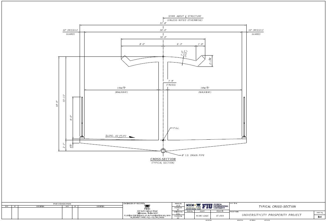
The proposal is a sales-pitch, and much of it reads very badly with hindsight, but there is no blame or shame in that. The picture above summarises some of the salient features of the design. The 5.5m tall concrete truss is conceptualised as a giant "I-girder", with the canopy overhead forming the top flange, the floor forming the bottom flange, and the diagonal truss members the web. The centre-to-centre distance of the flanges is around 5m, which is ample for a pedestrian bridge of this span. Here's the cross-section drawing from the proposal document:


Selection of a truss is in line with FIU's expectations: their own project specification identifies it as the most likely solution.

I've not found a clear explanation as to why concrete was preferred over the much more obvious use of steel for a trussed footbridge. MCM and Figg's proposal notes concrete's good vibration damping and thermal mass. The client specification permits use of both concrete and steel, although it does include a "Buy America" clause, which might make purchase of less expensive imported steel an issue.

The structure is all in post-tensioned concrete. The bottom slab is prestressed both longitudinally and transversely. The top slab is prestressed longitudinally. Most of the diagonal members are also shown as prestressed. A series of design drawings on pages 109-115 of the design-build technical proposal show the prestressing details proposed at the time of tender, and one of these is discussed further below.

Here is the general arrangement drawing from the technical proposal:


Diagrams in the proposal make clear that the structure did not require erection of the tower or stays during construction:


The explanation for the tower and stay system is twofold. Much is said about its relevance as a visual statement, the provision of a landmark structure. It can be seen that the truss arrangement has been adapted to suit the angle of the stays - this appears to be entirely for visual reasons, as you'll see shortly that the stays are not strongly connected to either the deck or the tower.

The diagram below makes clear the second reason for the stays, that they are there to alter the stiffness of the main span, bringing its vertical frequency above 3 Hz and hence out of the range for pedestrian excitation. This is a simplistic approach - I believe most pedestrian bridge designers would have accepted a lower frequency and dealt with the issue by more detailed analysis or by use of damping devices if necessary.


This diagram above states clearly that "the structure meets strength design criteria without the stays". The truss was designed to be strong enough on its own to carry its self-weight plus pedestrian loading. The stays are only there to control vibration, and for visual effect.

Some of this was evident from the photographs of the collapsed bridge. There are no conventional cable connections on the top of the truss structure, only concrete blisters with protruding bolt heads. These could not possibly carry the tension forces required in stays carrying significant loads. Here's the detail shown on the tender drawings:


Note that the stays are not shown as cables, but steel pipes. Even with pipes, it's doubtful whether with a truss as stiff as this, the stays would have sufficient axial stiffness to carry any significant share of imposed load. Reducing vibrations is the best that they can do.

Also note that the connection between the main span and the back span is nothing substantial. In a true stayed bridge, there would be a substantial connection at this point, to carry the longitudinal compressive forces in the bridge deck which balance the tension forces in the stays:


Probably the most interesting detail in the tender-stage drawings is one which shows the prestressing in the diagonal truss members:


In any truss node, quite a lot is happening structurally. The vertical forces in the diagonals will be in balance: in the drawing above, if the left-hand diagonal at the node is in compression, the vertical component of that compression will be matched by a vertical component of tension in the right-hand diagonal. The sum of the horizontal components of force in the two diagonals is balanced by a change in horizontal force between the left-hand and right-hand elements of the horizontal member, which on the drawing represents the roof slab.

As this is a prestressed structure, there will significant compressive forces in the node, with high localised stresses due to the proximity of the stressing bar anchorages. Taken together with the change in forces to be accommodated through the node, this is a highly complex design element, and one which would have been much easier to design in steel rather than in concrete.

Bridge collapse
It is also the exact location where work was taking place immediately prior to the collapse. The news reports make reference to "stress tests" being undertaken at the time. One engineer speculates about adjustments to precamber, although this would not be possible in such a stiff truss structure.

Two days prior to the collapse, the lead bridge design engineer phoned the Florida Department of Transportation (FDOT) to advise that cracks had been found in the bridge. In a statement, FDOT make clear that this message was left as a voicemail, and not listened to until after the bridge had collapsed. This does not seem very relevant, given that in the same statement FDOT acknowledge that their representative did attend a meeting with the project team early on the day of the bridge collapse.

A statement from FIU confirms that this meeting involved the contractor, designer, FIU and FDOT, and that a detailed technical presentation was made regarding the crack. The design engineer is reported by FIU as stating that there were no safety concerns regarding the crack.

Later the same day, work was taking place on the bridge directly above one of the truss nodes. A crane can be seen to be in place, and appears to have been supporting equipment, in two videos which show the bridge collapsing. The first is taken from surveillance camera footage, the second from a vehicle's dashboard camera. The best-quality version of the footage that I've seen can be found on Twitter:

As I write, it isn't clear what work was taking place, nor what the various organisations involved had been told about that work. The preliminary drawings indicate this to be the position of dead-end anchorages for the web prestressing, not stressing anchorages, but it's possible that was changed during detailed design.

The designers, Figg, and the contractor, MCM, have said little at this point of time (e.g. see Figg's statement). They probably have little choice: it is very likely to be a condition of their insurance that in the event of a legal claim arising the insurer takes control of what is communicated.

In the video, it can be seen that if the truss is conceptualised like a girder, a global shear failure occurs around the position where work is taking place. Shear in a truss is carried by alternating compression and tension in the web members, so it is possible that the overall failure was caused by failure of a single web member, or by failure of the connecting node.


It appears from the videos that the second triangular frame from the left (upward-pointing, directly below the crane) deforms, with all other triangles retaining their shape. The very first (downward-pointing) triangle on the left is largely non-structural: the vertical on the end is just there to support the future bridge pylon, while the horizontal upper member in this triangle is just there to carry the upper prestressing tendons to their anchorage.

This is as far as I will go in commenting; it is tempting to speculate further, but it can only be speculation. No doubt more information will emerge soon, possibly between my typing this and you reading it.

I am sure there will be more to discuss once further facts come to light. Only then will it be possible to consider what lessons there may be for others working in the bridge design and construction industry.

10 March 2018

"Danube-bridges" by Péter Gyukics

I was delighted recently to pick up a copy of "Danube-bridges: from the Black Forest to the Black Sea" (Yuki Studio, 330pp, 2010) by photographer Péter Gyukics. This is the English edition of a book also available in Hungarian and in German, which depicts every single bridge along the River Danube from source to sea.

Gyukics has two previous books of bridge photography, 2005's "Hidak Magyarországon" ("Bridges of Hungary"), and 2007's "Hidak mentén a Tiszán" ("Bridges along the Tisza"). I haven't had the good fortune to see either of those, but I am impressed by "Danube-bridges" and I would certainly like to do so.

The Danube is 2860km long, passing through or along the border of ten European countries. It winds through four capital cities: Vienna, Bratislava, Budapest and Belgrade. It has been significant both as a boundary and as a transport corridor, and today it is also an important source of hydroelectric power.

Gyukics took two years to photograph every single bridge on the main river, and the book features them in sequence from the confluence of the Brigach and Breg rivers where the Danube begins, down to the river delta where it empties into the Black Sea. He also includes bridges on the navigable side-channels of the river (such as the Danube canal through Vienna), for a total of 342 bridges shown in 962 photos. All the bridges are those that carry traffic of some sort, which is a shame as it means that utility bridges such as the spectacular gas pipe suspension bridge at Smederevo are not included.

The book is one-of-a-kind, as a combination travelogue and encyclopaedia. It's not the only photographic record of a journey down the Danube, but it is the only complete record of the river bridges.

The photographs are accompanied by text from bridge experts Ernő Tóth and Herbert Träger, giving whatever factual information has been gleaned on each structure, such as year of construction, key dimensions, designer, contractor, and a description of interesting features or historical aspects. Ernő Tóth is a prolific writer on bridges in Hungary, and those interested should check out the Első Lánchíd website for more.

The book features useful maps, a detailed index, and a series of useful introductory sections, including a detailed and informative description of the river written jointly by a geologist and a hydraulic engineer.

The smallest bridge spans only 9m; the largest 351m. The bridges date from 1146 to the present day, although the majority have either been built or rebuilt within the last 75 years. This is a book of contemporary photography, so although older bridges on each site are described, there are no historic photos or images. Those can in some cases be found elsewhere, for example, the bridges in the Hungarian stretch are covered in more detail in the excellent book "Duna-hídjaink", which is freely available online. One of the oldest and longest bridges across the Danube, Constantine's Bridge, is an absentee (because it no longer exists), while the famous Trajan's Bridge is represented only by its remaining ruined foundation.

Gyukics has done well to find good vantage points to see the majority of the bridges, some of them photographed from the air or from boats on the river. The journey starts out slowly, with many pages of spans which are undistinguished although not entirely without interest. These are mostly fairly anonymous highway, rail and footway bridges in rural Germany. There are a few oddities to be found this high on the river, but what strikes me most is how much variety there is within the mundane. There are almost no two identical bridges, even where the same river crossing problem is solved again and again. Minor features of the context, and differences in approach by individual engineers, lead repeatedly to subtly different outcomes. There is plenty here for anyone who mistakenly thinks engineering is a science, rather than an art.

Although the photos focus upon the bridges, there is plenty to see in the countryside, as well as those who use the bridges. As the book proceeds, the possibilities in structural engineering steadily expand, while the scenery shifts gradually. Flip forward a few pages at a time and what is initially imperceptible becomes clearer, as the river increases in volume and comes steadily to dominate the landscape.

There are several bridges which are frankly dull, at least to begin with, but interspersed with cute little covered timber bridges, and more than a few interesting and unusual concrete and steel designs. Moving downstream, there is an increasing number of steel trusses, which accumulate until they become the Danube's dominant bridge form. It's tempting to try and pick out highlights, but there are so many structures that any bridge enthusiast should find something that delights or surprises. You can find thumbnail samples for most bridges at the publisher's website. Along its way, the Danube features some world-famous spans and well known designers, as well as a number of bridges which are structurally or architecturally remarkable.

There is a box girder bridge with a secret railway passing inside the box; a cable-stayed bridge with a cafe at its top; several arch bridges so thin they appear unstable; bridges with legs that look like inverted pyramids; an Austrian variation on Sergio Musmeci's thin-shell experiment in Basento; a twin-deck structure which lifts its lower deck when boats pass, like hitching up a skirt; and plenty more which are weird, wonderful and amazing.

It's impossible not to begin to spot one key reason behind the variety of structures, and the explanation why there are so few older structures. Many of the bridges are described as having been damaged or destroyed in the Second World War, and having been rebuilt since. The same is noted for bridges in Serbia, many of which were affected by NATO's air strikes in 1999. In times of war, access to river crossings is key, and the history of the Danube's bridges provides a reminder that bridges often play a  key role in peaceful trade and cooperation, and hence become particularly vulnerable in times of conflict.

The text is not always well translated into English, but it's quite good enough. Knowing that "permanent height" should instead be "constant depth" and that "belt" should be "chord" will resolve most of the more peculiar captions.

Copies of the book are available directly from the publisher, priced at €20 plus postage. For the UK, that worked out for me at €35 total, which is very good value for a full colour book of this size and length, although I had to pay bank transfer fees on top of this.

02 March 2018

Rotherhithe Bridge "controversy"

A couple of weeks ago, the architectural trade press reported a controversy on the procurement of Transport for London's proposed Canary Wharf to Rotherhithe crossing.

Following a detailed feasibility study, which looked at options for a ferry, tunnel, or opening bridge for pedestrians and cyclists at this location, TfL identified the opening bridge as their preferred solution. They undertook a public consultation, which ended in January. Meanwhile, they elected to push appointment of a design-and-build contractor to build the bridge back down the track. Instead, TfL are now looking to appoint a design team to develop a reference bridge design capable of securing consent under a Transport and Works Act Order.


The project has a history which in some ways brings to mind the Garden Bridge fiasco. It seems that the Rotherhithe scheme was not originally TfL's idea. Back in 2013, a bridge was proposed by reForm Architects, working with engineers Elliott Wood. ReForm's concept was for a double-leaf cable-stayed bascule structure (pictured), and they devoted quite considerable effort to promoting the concept and developing it further.

ReForm teamed up with cycling charity Sustrans to undertake a feasibility study, which demonstrated clearly that a bridge at this site could be highly valuable (although it is notable that the 2016 Sustrans report makes no mention of the reForm concept design). Ever since, reForm have remained tenacious in promoting the project, even setting up a "Save Rotherhithe Bridge" website, and asking Buro Happold to join their team to add credibility.

Recognising the merits of the proposed pedestrian and cycle crossing, TfL set out to investigate options for themselves, appointing consultant Arcadis from their engineering services framework. Arcadis teamed up with ubiquitous bridge specialists Knight Architects. The outcome of their study forms part of the public consultation material, with a clear and sensible report which evaluates the various issues without settling on a definitive solution.

The Arcadis/Knight report does however take against the reForm/Elliott Wood proposal, noting that a 150m span double-bascule bridge would be a world record-breaker (by some margin), while swing and lift bridges are more proven forms at this span length.

TfL are looking to appoint a team to produce a reference design (and take it through the Transport and Works Act process) from the same framework panel where they found Arcadis. At this point, reForm and Elliott Wood have cried foul, stirring up an utterly unmerited controversy in the press.

Construction News reports that there may be a "conflict of interest", on the grounds that Arcadis recommended against the bascule solution, and have therefore developed a brief which prevents competitors from participating.

It's hard to know where to begin with this nonsense. Reading the Arcadis report, it's clear that a bascule solution is not favoured, but nor is it ruled out. ReForm's problem is that they are not on the TfL framework. However, there is absolutely nothing preventing them from teaming up with one of the consultants who are on the framework. The real problem is their unwillingness to depart from their original design. TfL appear to be seeking a team who will properly evaluate the options and take forward the best one: not a team who are so committed to a single idea that they may tie TfL to an unsuitable outcome.

Indeed, the bascule design hardly seems like the best bet. 75m long bascule cantilevers will be a problem to operate in high wind conditions. The cable-stayed arrangement means that the centre of gravity is remote from the centre of rotation, with the result that energy requirements during operation are higher than for a better balanced design (such as a swing bridge or lift bridge).

Should TfL have opened up bidding beyond their framework? Again, this seems ridiculous: their framework consultants are generally large firms with plenty of expertise, and who are free to supplement their teams with niche specialists where they need to. Arcadis have no particular advantage as the incumbent, as the skills required for the previous phase may not be those needed going forward. TfL have made clear that they are looking at this stage for the right team, not a single design.

ReForm's complaint is that as a small firm, they are disadvantaged, but there is no reason whatsoever why TfL should not follow its existing procedure for procuring appropriate expertise. Presumably all the firms on their consultancy framework have already demonstrated that they can comply with TfL's general commercial and quality requirements, and will be providing further appropriate detail if they bid for the next stage.

Imagine if reForm had been appointed in place of all these firms to develop this project. Is it not overwhelmingly likely that those who had already bid for a place on the framework, jumping through multiple prequalification and tender hurdles to do so, would then be crying foul?

Indeed, if TfL were to bend over to create a way in for reForm Architects, they would be accused of exactly the same failures that allowed Heatherwick Studio and Arup to win the Garden Bridge contract in the face of better-scoring opposition. As with reForm, Heatherwick already had a concept design, and no real interest in evaluating alternatives to it.

If TfL genuinely want to do the best for their London taxpayers, then they should instead be applauded for the transparency and openness of their approach, carefully evaluating alternatives, gathering evidence, and making sure that the case for building the Canary Wharf to Rotherhithe Crossing is properly merited. Having done so, they are quite right to be considering all the options in more detail before settling on any specific design.

There is no conflict of interest here, and no real controversy.

Move along.

20 February 2018

"The Bridges of Medieval England: Transport and Society 400-1800" by David Harrison

This blog normally focuses on contemporary bridges and their designs, although I do also often cover historic bridges. I have featured a few medieval structures over the last few years: PostbridgeTwizel Bridge, Old Powick Bridge, Devil's Bridge, Framwellgate BridgePont Saint-BénézetPont Neuf, as well as the Roman Pont Du Gard.

David Harrison's book The Bridges of Medieval England: Transport and Society 400-1800 (Oxford University Press, 2004, 269pp) [amazon.co.uk] is an in-depth investigation of a period which is sometimes sidelined in histories of bridge building. Unlike more recent periods of history, there is simply less written evidence from the medieval period, less knowledge about what was built, by who, when, or for what reason.

Harrison's book is a conscious attempt to redress the balance, and to correct misconceptions about a period where the lack of evidence often leads to mistaken assumptions. The book is meticulously researched and referenced, often from primary sources, and builds a surprisingly detailed picture of the extent of bridge-building in medieval England.

The book is divided into three broad sections.

The first is a quantitative survey, considering how many bridges were built, where and when. Harrison's core argument is that historians have grossly underestimated the sheer quantity of bridges built in medieval times, and that in doing so they have misunderstood the organisational and economic capacity of society in that period.

Surveying a range of historical records, the author deduces that there were almost as many bridges in existence in 1250 as there were some five centuries later, and that many of these bridges dated back to Anglo-Saxon times. He also makes the case that most of these bridges were on roads freshly introduced after Roman times, rather than relics from the Roman occupation. If some of the evidence for earlier periods is somewhat tentative, for later centuries Harrison is able to tabulate numbers of bridges in impressive (albeit often laborious) detail.

The story is one of slow changes in transportation in early medieval centuries, with fords gradually giving way to bridge construction, generally in timber (or timber on stone piers). By the later medieval period, the picture changed to consolidation, with fewer new sites for bridges as most rivers were already bridged at key points, and a gradual conversion of timber structures into stone arch bridges. With written sources often sparse or incomplete, there is a great deal of detective work e.g. by considering place-names such as Bristol, first mentioned as Brycgstow in 1063 ("the site of the bridge").

The books's second part deals with the bridges as structures: their form and materials, and methods of construction. Here the evidence is much stronger, as over 200 medieval English bridges survive today. Bridges built elsewhere in Europe often have the same forms from the same periods.

Little information has survived on how medieval bridge-builders designed their structures: writings on the subject only really started in the 16th century, with the first book in English not published until 1772. Nonetheless, the key concern of the medieval bridge builder was clear: how to survive the elements. London Bridge, completed in 1209, was well-known for how it restricted the river flow, resulting in a huge difference in river levels above and below the river during peak tidal changes. Many early bridges had wide piers and narrow openings, and the history of many medieval bridges is one of occasional collapse, damage, and repeated repair and rebuilding.

Vulnerability to hydraulic forces, and to scour, meant that much of the art of medieval bridge building lay in selecting suitable places for the foundations, and suitable foundation construction. Harrison distinguishes between the large spans of the northern uplands (such as Twizel Bridge and Devil's Bridge), relying on rocky ground for support and providing clear flow for torrential rivers, and the often multi-span viaducts of the southern lowlands, often founded on poor ground and supported on timber "sole-plates" or timber piles driven into the earth. The invention of pile-driving was evidently one of the most significant achievements in the development of medieval bridge building.

There is plenty of interesting material here for anyone involved in conservation of old bridges, or just interested in understanding the challenges the bridge-builders faced, and how they were resolved. As well as presenting the factual details, Harrison is keen to address another misconception - that the many reports of problems with bridges indicate widespread problems with the condition of structures. Instead, he argues that bridges were generally well-maintained, with very few out of service at any given time.

The final section of the book is titled "Economics and society", considering costs of construction, and how bridge building and maintenance were funded. The picture here is of a society willing and ready to spend significant sums of money on a bridge and road network which was critical to trade. However, the mechanisms for funding were very different from today.

Funding for construction was generally private, through wealthy lords and landowners. Maintenance was funded in the same way, as well as from charitable donations (including religious indulgences), from tolls, and through legal obligations. The last of these dated to the Anglo-Saxon period, when "bridgework" was a duty required of certain local communities, along with duties to maintain fortifications and to participate in military service. The "bridgework" obligation fell away only slowly, with a gradual process of lifting of these duties as town charters were renewed or legal challenges made. There was an increasing tendency to place obligations onto bodies with a greater longevity than landowners and residents, with a shift towards the English counties following the 1530 Statute of Bridges.

Some bridges benefited from the establishment of an endowment, lands from which the income was to be used for the management and maintenance of the bridge. Two well known examples survive today: the Rochester Bridge Trust, and London's Bridge House Estates.

This book's main flaw is a lack of illustration. There are a few maps, and 27 historic photographs and illustrations of relevant bridges, but it would have benefited greatly from pictorial explanations of the different forms of bridge construction, and from having some of the more detailed information presented more accessibly (e.g. timelines, tables, and charts).

It is not a book aimed at the casual pontist or perhaps even the armchair historian. It is thorough and detailed, and principally addressed to specialists in medieval history, or the history of transport and economics. However, it is a very impressive piece of work, and I think it should certainly be on the bookshelf of anyone who is serious about the history of bridges in England.