I will therefore try to be cautious and factual in what I say, as it seems clear that the reasons for the bridge collapse will be better identified and shared by those with full access to the facts. The desire to rapidly identify causation (and to lay blame) is understandable, but I would like to minimise speculation.
Media coverage
Much of the coverage in the press has been ill-informed guesswork, attempting to draw together whatever half-truths have emerged in order to flag issues which may or may not ultimately prove to be meaningful.
Prime suspects identified by the media include past failures attributed to the two main design-and-build companies involved in the FIU bridge project, MCM (the contractor) and Figg (the designer). Repeated quality failings are a possible issue, but my experience is that there are almost always many contributing causes to any serious failure.
There are even less likely culprits put forward on Twitter: Trump (of course), a false-flag conspiracy, immigrant labour, and most egregiously of all, "diversity-hiring". For the sake of our sanity (often difficult when reading Twitter), I'll say nothing more about these and return to the suspects fingered in the mainstream media.
"Innovation" is linked by one engineering professor to "unexpected failure", as if to imply that innovation is always too risky an approach to take. He may have been misquoted, but this criticism is repeated elsewhere, giving the impression that 'doing new stuff' is so dangerous that it should never be attempted. Says the prof: "Innovations always bring potential 'failure modes' that have not been previously experienced".
There's no doubt that innovation can introduce new risks, but these are normally managed through appropriate review and risk management. I've seen nothing to suggest that the designer, checker, contractor, highway authority (Florida Department of Transportation, FDOT), or owner's engineer (TY Lin) had any doubt about the safety of any of this bridge's innovations in advance. In any event, it is clear from TY Lin's project specification that innovation was something their client would evaluate positively: they actively sought it out.
What innovation is at issue anyway? Many of the news reports point the finger at Accelerated Bridge Construction (ABC), the method adopted by the contractor to install the bridge span across a busy highway with as little disruption to traffic as possible. Ironically, ABC is something that FIU have a keen interest in, and in promoting their bid to build the bridge, the MCM-Figg team enthusiastically drew attention to the connection.
ABC refers to a family of methods for building bridges faster, usually more safely, and often cheaper. The common elements are the use of offsite or modular pre-construction techniques, so that bridges are assembled in-situ as quickly as possible, rather than built entirely in place. Engineers promoting ABC techniques in the US have come up with some excellent ideas, but it isn't fundamentally anything special, and rapid-installation techniques are widely used around the world. For a bridge such as the FIU Pedestrian Bridge, spanning a busy highway, you'd have to be asking serious questions of anyone who didn't adopt an ABC approach. Again, FIU's project specification made clear that ABC techniques would be acceptable, setting out associated construction requirements.
The span which collapsed was the first of two spans due to be installed, and is a simply supported concrete truss bridge designed to sit on its end-supports without any further temporary support (or indeed, permanent support - more on that later). It was built nearby and then wheeled into place on self-propelled modular transporters (SPMTs), an increasingly common way to build a bridge. In addition to reduced traffic disruption, a key driver for this was the presence of overhead power lines at one end of the bridge, which made craneage a less attractive approach. You can see the power lines at the left hand edge of a general arrangement drawing shared on Twitter:
.@NTSB_Newsroom officials say workers were working on strengthening the north side of the #fiubridge during the collapse. @MiamiHerald pic.twitter.com/nspRErAk7f— Monique O. Madan (@MoniqueOMadan) March 17, 2018
Accelerated bridge construction is cited often in the initial news coverage of this disaster, but it is not in itself relevant, given that the bridge span was designed to span between its piers in both the temporary and permanent cases. More on this below.
Another 'issue' cited often in coverage is simply why the span was allowed to remain in place above live traffic. The highway authority, FDOT, have been at pains to rapidly disassociate themselves from the project, but have stated that it was their role to "authoriz[e] FIU to utilize the aerial space above the state road to build a structure".
My personal experience of building new bridges above existing highway or railway infrastructure is that the infrastructure owner takes a keen interest in the safety of the construction work, especially where the infrastructure will remain open to traffic prior to completion of the bridge. In the UK, they would undertake a full technical approval process, not checking the design, but assuring themselves that the teams involved are competent, that the processes in place are appropriate, and that risks have been properly identified and managed. Where a bridge will be in a temporary state with traffic running below, my experience is they take this very seriously.
Perhaps in the US it is different, but I would have thought that the primary responsibility for the safety of highway users lies with the highway authority, and that in agreeing to "authorize utilization of aerial space above the state road", they would take a keen interest in the details of what was proposed. Presumably they have the power not to permit the work to go ahead if they have any concerns.
In this case, however, there should have been no great concern about running traffic below the bridge: it was, as we will see, designed to span the highway without additional support, and to be able to carry full live loading in the same configuration. The design load required in FIU's specifications is 90 psf (4 kPa), on a span 31-feet (9.4m) wide by 175-feet (53.3m) long; a total live load of roughly 200 tonnes. It was clearly carrying nowhere near this load at the time of collapse.
Much of the initial commentary has noted the obvious disparity between the bridge's temporary condition (a concrete truss spanning simply supported), and the final cable-stayed arrangement shown in design visualisations (and on the drawings):
The suggestion is made that the bridge could not be expected to stand up without the stays in place, which would of course also require the tower to be complete, and the back-span, and the back-span abutment. All of these can be seen on the general arrangement drawing shown above (and on what you will see below).
Tender-stage design
However, the bridge was not designed to rely on the stay system. There are quite a few documents relating to the project online at the FIU's project website. For details of what was being proposed at tender stage, refer to the technical proposal from MCM and Figg. The images and drawings that follow are taken directly from that document. It must be emphasised that the final construction design may have been different, although I have not seen anything in photographs of the bridge which differs from these early drawings.

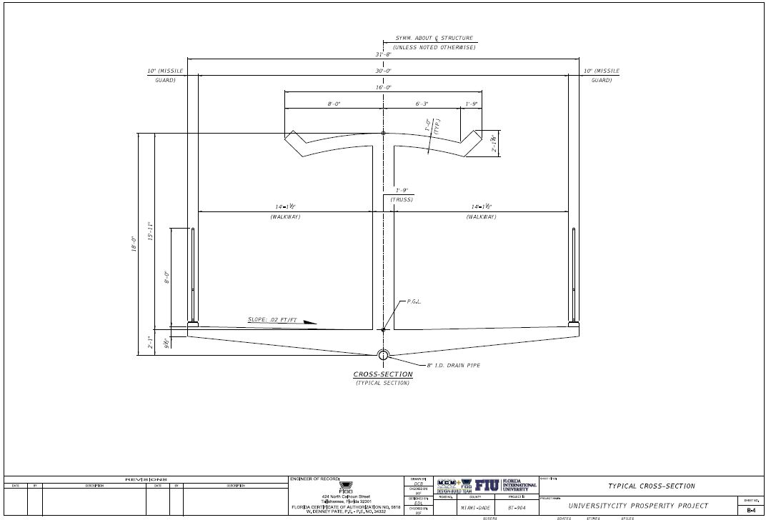
The proposal is a sales-pitch, and much of it reads very badly with hindsight, but there is no blame or shame in that. The picture above summarises some of the salient features of the design. The 5.5m tall concrete truss is conceptualised as a giant "I-girder", with the canopy overhead forming the top flange, the floor forming the bottom flange, and the diagonal truss members the web. The centre-to-centre distance of the flanges is around 5m, which is ample for a pedestrian bridge of this span. Here's the cross-section drawing from the proposal document:
Selection of a truss is in line with FIU's expectations: their own project specification identifies it as the most likely solution.
I've not found a clear explanation as to why concrete was preferred over the much more obvious use of steel for a trussed footbridge. MCM and Figg's proposal notes concrete's good vibration damping and thermal mass. The client specification permits use of both concrete and steel, although it does include a "Buy America" clause, which might make purchase of less expensive imported steel an issue.
The structure is all in post-tensioned concrete. The bottom slab is prestressed both longitudinally and transversely. The top slab is prestressed longitudinally. Most of the diagonal members are also shown as prestressed. A series of design drawings on pages 109-115 of the design-build technical proposal show the prestressing details proposed at the time of tender, and one of these is discussed further below.
Here is the general arrangement drawing from the technical proposal:

Diagrams in the proposal make clear that the structure did not require erection of the tower or stays during construction:

The explanation for the tower and stay system is twofold. Much is said about its relevance as a visual statement, the provision of a landmark structure. It can be seen that the truss arrangement has been adapted to suit the angle of the stays - this appears to be entirely for visual reasons, as you'll see shortly that the stays are not strongly connected to either the deck or the tower.
The diagram below makes clear the second reason for the stays, that they are there to alter the stiffness of the main span, bringing its vertical frequency above 3 Hz and hence out of the range for pedestrian excitation. This is a simplistic approach - I believe most pedestrian bridge designers would have accepted a lower frequency and dealt with the issue by more detailed analysis or by use of damping devices if necessary.

This diagram above states clearly that "the structure meets strength design criteria without the stays". The truss was designed to be strong enough on its own to carry its self-weight plus pedestrian loading. The stays are only there to control vibration, and for visual effect.
Some of this was evident from the photographs of the collapsed bridge. There are no conventional cable connections on the top of the truss structure, only concrete blisters with protruding bolt heads. These could not possibly carry the tension forces required in stays carrying significant loads. Here's the detail shown on the tender drawings:

Note that the stays are not shown as cables, but steel pipes. Even with pipes, it's doubtful whether with a truss as stiff as this, the stays would have sufficient axial stiffness to carry any significant share of imposed load. Reducing vibrations is the best that they can do.
Also note that the connection between the main span and the back span is nothing substantial. In a true stayed bridge, there would be a substantial connection at this point, to carry the longitudinal compressive forces in the bridge deck which balance the tension forces in the stays:

Probably the most interesting detail in the tender-stage drawings is one which shows the prestressing in the diagonal truss members:

In any truss node, quite a lot is happening structurally. The vertical forces in the diagonals will be in balance: in the drawing above, if the left-hand diagonal at the node is in compression, the vertical component of that compression will be matched by a vertical component of tension in the right-hand diagonal. The sum of the horizontal components of force in the two diagonals is balanced by a change in horizontal force between the left-hand and right-hand elements of the horizontal member, which on the drawing represents the roof slab.
As this is a prestressed structure, there will significant compressive forces in the node, with high localised stresses due to the proximity of the stressing bar anchorages. Taken together with the change in forces to be accommodated through the node, this is a highly complex design element, and one which would have been much easier to design in steel rather than in concrete.
Bridge collapse
It is also the exact location where work was taking place immediately prior to the collapse. The news reports make reference to "stress tests" being undertaken at the time. One engineer speculates about adjustments to precamber, although this would not be possible in such a stiff truss structure.
Two days prior to the collapse, the lead bridge design engineer phoned the Florida Department of Transportation (FDOT) to advise that cracks had been found in the bridge. In a statement, FDOT make clear that this message was left as a voicemail, and not listened to until after the bridge had collapsed. This does not seem very relevant, given that in the same statement FDOT acknowledge that their representative did attend a meeting with the project team early on the day of the bridge collapse.
A statement from FIU confirms that this meeting involved the contractor, designer, FIU and FDOT, and that a detailed technical presentation was made regarding the crack. The design engineer is reported by FIU as stating that there were no safety concerns regarding the crack.
Later the same day, work was taking place on the bridge directly above one of the truss nodes. A crane can be seen to be in place, and appears to have been supporting equipment, in two videos which show the bridge collapsing. The first is taken from surveillance camera footage, the second from a vehicle's dashboard camera. The best-quality version of the footage that I've seen can be found on Twitter:
Breaking Video: Dramatic dash cam footage shows the moment of the bridge collapse at FIU. pic.twitter.com/bm63EncDTj— PM Breaking News (@PMBreakingNews) March 17, 2018
As I write, it isn't clear what work was taking place, nor what the various organisations involved had been told about that work. The preliminary drawings indicate this to be the position of dead-end anchorages for the web prestressing, not stressing anchorages, but it's possible that was changed during detailed design.
The designers, Figg, and the contractor, MCM, have said little at this point of time (e.g. see Figg's statement). They probably have little choice: it is very likely to be a condition of their insurance that in the event of a legal claim arising the insurer takes control of what is communicated.
In the video, it can be seen that if the truss is conceptualised like a girder, a global shear failure occurs around the position where work is taking place. Shear in a truss is carried by alternating compression and tension in the web members, so it is possible that the overall failure was caused by failure of a single web member, or by failure of the connecting node.

It appears from the videos that the second triangular frame from the left (upward-pointing, directly below the crane) deforms, with all other triangles retaining their shape. The very first (downward-pointing) triangle on the left is largely non-structural: the vertical on the end is just there to support the future bridge pylon, while the horizontal upper member in this triangle is just there to carry the upper prestressing tendons to their anchorage.
This is as far as I will go in commenting; it is tempting to speculate further, but it can only be speculation. No doubt more information will emerge soon, possibly between my typing this and you reading it.
I am sure there will be more to discuss once further facts come to light. Only then will it be possible to consider what lessons there may be for others working in the bridge design and construction industry.
28 comments:
Excellent article!
The mayor tweeted that the cables (bars) had loosened and were being tightened when it collapsed.
There is a picture that shows one of the bars on the relevant diagonal with a prestressing jack attached after the collapse. There is no jack still attached to the other bar after the collapse. The picture could suggest that the top dead end on the design drawing only applies at the acute diagonal at the other end.
https://imgur.com/gallery/2G5Fk
A similar cable stayed bridge in Canada failed two years ago when cables were being tightened. There were no injuries or fatalities.
Ref: Nipigon River Bridge.
Google & Wikipedia have lots of information.
Thank you for the well written summary. There is so much bad information out there. As a bridge engineer in the states, every state I worked in will "review", but not "approve" the plans. Every state I have worked in also requires a PE stamped erection plan and some states require inspection of girders etc, and a PE stamped certification that it is safe to open the road under the bridge (or partial bridge) to traffic.
Additionally in my experience on Design Build projects there are significant QA/QC requirements and ABC projects usually get extra scrutiny. I did see a report that an independent technical review was required and performed by Louis Berger Inc.
Thanks for the good wrapped info on the subject. I find it quite brave to tension on Live traffic without any measure.
Looking forward to hear more on the diagonals.
Someone remove the cable the truck crane, so the truss are compressed and stressed , but in servicio final will be strain for the stayed bridge...
Nice writeup. Calif S E here. From about 2PM my time Thursday, seeing the first pics on cable,I thought it likely that the north truss heel joint had failed. Now we see how it was transported - with support under the first interior bottom panel points, and that reverses the force directions in the end diagonal (to the heel) and the next interior diagonal while under transport. The original proposal/prelim dwgs did not show PT in the end diag, but that was probably added when the cantilever condition was addressed.
We heard of cracking, but I have not seen a description of where and how it propagated.
We can now see a PT rod with blue jack protruding from the top of the north segment of roof. The rod and jack are almost horizontal because the section of roof and diagonal are tipped down about 50 degrees. The rod has pulled from the diagonal maybe 4 feet. This was probably the "adjustment" to PT that was noted in press releases. If the cracking was at or around the base of the diagonal and end column, tightening the PT may have been intended to close or resist the cracking. Not good - at the time, the diagonal had about 1600 kips of compression - it did not need more from the PT. Why did the rod pull out so far? The jack did not pull it out - it was pushed out on the way down. Why was the PT loose? It was under maybe 100 kips tension when shored and transported - then changed to 1600 kips compression in place - it shortened.
The horiz component at the heel is about 1300 kips, induced by the diagonal at the heel. Wonder if there is a pour joint at the top of the deck slab? Can't see any drawings of reinforcing -
So if the end diagonal is lost - in whatever manner - the truss action is lost and the deck slab must cantilever from the first bottom panel point to the support - 940 kips at about 28 feet away - the moment is about 26,000 ft-kips. For truss action at DL about 2600 kips of PT is needed at C/L. That moment would require 26000 kips of ultimate capacity PT at a depth of 16" below top of deck (8.5" deep compression block at 8500 psi concrete stress). So the deck fails near the first bottom panel point, that point drops, the deck is pulled off the pier, and now rests neatly at roadway elevation and almost touching the south face of the pier. Can't see the condition of the edge of the deck at center from 3000 miles away - always in shade - but much of the vert column is still atop the pier and the diagonal is almost connected to the column.
A general comment - it would be great to know they provided a lot of confinement reinforcing at the joints of this truss - and some reinforcing to add continuity and aid the load transfer. Also the prelims show two PY rods at the top of the end columns which connect the two bridge spans together. At that point they will draw negative moment and reverse some stresses in the truss. Something to think about. Also - can't help but wonder if vortex shedding may cause vibrations in the 16" pipe "stays" - with 10 in the breeze they make more than an octave - perhaps they could be tuned.
Good thoughts and prayers are being sent up for the victims and their families. This is a terrible tragedy.
Thank you,
VW
good insight...
For both spans-- the long one that collapsed-- and the short one not yet built--- It is interesting to note that the # of PT Bars and the overall PT rod force -- greatly increases the closer the diagonal members are to the Center Pylon.
There are 2 large unknowns-- 1. what was causing the cracking (and where was it)?
2. Was this cracking the reason why they were field adjusting the PT bars ?
Blimey...the pommie beat me to it..def it is shear issue..not most steel and wood trusses would have vertical chord as well..this one doesnt...vertical chords would have saved the day..design flaw...
Another..posttensioning chords is a bad
Should have been regular concrete
..my rough numbers...factored shear ~ 1000 kips..concrete shear capacity at the node~ 800 kips..so in deficit...all dead loads here...now pt rods add to capacity was being destreesed at EORs request...w this dowel effect gone...boom....
The top slab & most of the diagonal elements are under serious compression by default. Don't really see a reason nor understand the use of prestressing on them!!! Most likely leads to overstressing
Thanks for the article and references.
For some of the other commenters: since the span had to be designed for the cantilever situation during erection as well as the simplified single span, the PT adjustability was beneficial. Not all elements of the top flange were continuously in compression.
Thanks again for the article.
Sorry for the loss. Another reason not to build a fracture critical structure when there are plenty of options.
The choice of concrete reinforced for the complex structure of 200 tons weight for a pedestrians bridge use, above a heavy traffic city highway would have been more efficiently design with traditional technologies as even better with update composites engineering much lighter solutions and the relevant approach to easier finite elements solutions of the complexity of the connections of the sections and the potential interferences with local environmental conditions of use. The case - thanks to the detailed description of the design - could become a model to treat and use for the expected proposal of fullfillment of the project. Vincenzo Lo Scalzo, Lo Scalzo Associates snc
Here, too, I read that there were still pre-stressed activities at the moment of collapse. This means that the channels were not yet filled with injection mortar. Due to the small cross-section and the high pulling force, the prestressing steel has the property to extend a lot. By applying an extra pre-tension, this effect is increased at the moment of anchoring. This could explain the distortion in the bridge element that is being discussed. Due to the deformation, the pressure rod of the adjoining box gets an eccentricity. This creates an additional bending moment in the bottom bar. This may have caused the collapse. That is not counted on. Extra distortion of the not yet filled tensile bars is, in my opinion, important here. I would also like to see the upper detail of the connection where the bridge collapsed. How is the termination of the pre-tension bars detailed. This should be different than the detail shown. The forces must cancel each other out.
Today Mar 20 NTSB is looking right at the problem - check their video. The PT has peeled out of the underside of the end diagonal - that is the same PT with jack that is protruding from the concrete and which was being "adjusted". That strand is seen inside its duct curling back to the end anchor which must still be embedded in the deck slab. The "peel back" and the apparent fact that the PT anchorage remains in the deck slab suggests a shear failure at the pour joint between the deck surface and the end diagonal. There was about 1300 Kips shear across that joint.
The PT peeled out of the diagonal because the bottom of the end column and the bottom of the end diagonal essentially remain atop the pier and the slab pulled the anchorage to the roadway when the deck fell. The difference in dimension between the horizontal positions and the original diagonal length pushed the PT and jack out of the upper concrete. That PT strand is dangerous in a bent state should the anchorage come loose - it is a bent spring waiting to straighten. Needs some care there.
The end diagonal was carrying about 1600 Kips at the time of the failure. The tie size and spacing seems - -sparse. But apparently they held the longitudinal reinforcing in place at the corners. And the PT tearout is not a condition one designs for.
I am thinking the decision to "adjust" the PT may not have been the best one. Adding PT increases the horizontal thrust at the joint if the bottom anchor is in the deck - but it also increases the normal force. If the joint has allready slipped, I am doubting you can get ahead of it that way.
Vincenzo - it is much heavier than you mention - the prelim drawings show 915 tons, the press is saying 940 tons.
VW
I've been posting comments to the "engineers" on YouTube but this analysis is spot on. What we have here is an asymmetrical cable-stayed bridge without the pylon and stay cables. Couldn't hold itself up without the stay cables. The diagonal labeled #11 in some schematics was under compression and if they were tightening when the bridge fell,the additional downward force triggered the failure.
It's not a question of building technique, it's a question of building sequence.
This is a response sent only to one person in regards to a fracture critical structure comment - repeated here if anyone else is interested.
Right on target. And for the less technical - the very reason limits are placed on the amount of reinforcing in concrete structures - to ensure any failure should develop in the reinforcing and remain ductile and can (maybe) develop slowly. And the focus returns to the cracking reported. Was it the beginning of the "ductile failure" phase - which in this case was pretty short, time wise?
Think of the decision to be made when the cracking was first observed - do you stop traffic because you saw a small crack and it might not be significant? Doing so would will blemish the ABC banner of the project which is obviously of great importance. If the cracking is critical, can it be corrected in place? Does it need temporary support? That will require about 600 tons of shoring and quickly - not sure two cranes are big enough - and how would a crane lift it? Do you send men under it and erect shoring? That could take maybe days for that much capacity. Is there time? Is the mobile transport still on site? That will be an expensive decision - what if it is not really necessary? What if you have a meeting and three hours later it collapses and 6 people die?
Hindsight can provide great clarity - but by definition, it develops too late.
A great great loss for everyone.
A sense of what might have been intended is growing here. It begins with noting the preliminary detail over the middle pier where the trusses of the two spans abut. At the top it is shown that they are to be connected with two PT strands - capable of 320 kips each or 640 kips total. At 12 feet above the deck that can cause/resist negative moments of 7680 ft-Kips (more at failure loads). If tightened under dead load conditions it will introduce negative moments only under live load conditions - ideally speaking. Either way, the connection has the capacity noted and can draw reactions to the middle pier which increase the shear in the interior ends of the trusses - about 80 kips at the pier end of the north span and maybe 50 kips at the pier end of the south truss. But this negative moment will not develop if the columns shear just above the PT (12').
Which concept leads to the point that back to back columns grouted tight, as shown on the prelims, and clamped tightly so they cannot separate, will cause the thrusts from the north span to resist the thrust from the south span, possibly preventing failure like that experienced. It would need to 'live' long enough as a stand alone truss to allow the north span to be in place and provide help in this way.
I saw mention of provisions provided to change bearing pads - does that require lifting the end to R/R the bearing pads? Not good if the two spans are connected (lift both?) or if the closure is anchored to the pier thru reinforcing. I have no experience in this replacement procedure - how is it generally conducted?
Excellent analysis. Even without knowing details I also wondered why Cable stays were necessary. Since the truss with top and bottom slabs can be considered as an I section with open web. If its height is 5.5 m then it is more than sufficient to span 175 ft. Bottom slab needs prestressing to counter bending tension. Top slab which would be in compression would not need longitudinal prestressing. Lateral stability (along the road traffic direction) of the single girder would be achieved through deeper 'beams' seen below the slabs at both ends of the span and also slabs spanning as diaphragms in horizontal planes between end pillars.
As mentioned in the analysis cables stays were apparently more for appealing view.
Steel trusses (or steel members encased in concrete) would have been a much lighter and simpler structure.
just wondering,
what is providing the lateral stability to the single truss?
top flange being the roof is connected at the top nodes of the truss, developing torsional stresses at the interface of ceiling
Vasant and Anonymous - I also have concerns about the lateral stability of the compression element of the truss, particularly in a case where all the pedestrians might move to one side, perhaps to watch an oncoming parade. This would induce torsion which could only be resisted by the roof (top flange) spanning from pier to pier. The only thing I see which could transmit that accumulative horizontal thrust down to the pier is the single vertical column at the ends of the truss. The web members along the span cannot - they are the elements delivering the side thrust to the roof. The roof slab is a foot thick with stiffened edges and 16 feet wide, spanning 174 feet - that is less than a 12:1 span/depth ration - so that ratio looks OK.
The roof is post-tensioned to reinforce for the horizontal bending moments induced by the lateral bracing demand and the effects of hurricanes. The use of post-tensioning in the roof comes with a cost - it has to be offset by an equal amount pf PT added to the bottom deck PT.
I see no evidence of lateral instability causing the collapse - it dropped in a straight fall, it appears.
My primary concern is the lack of redundancy -- the single truss has none, as has been so tragically demonstrated in the failure of one member or joint. Of course the cable stayed bridges will also fail if the column/mast supporting the cables fails. I suspect the mast is built to be quite stout.
Now for my question - did anyone see them lift the bridge 4 feet above the top of the pier and drop it over the two PT rods which are to bolt the end of each truss to the center pier" Can it slip and accommodate dimensional changes due to temperature and be bolted down? Maybe that was changed in the final drawings? Are the bearing pads needed if it is bolted?
As the engineer's joke says "I think I see the problem" - NTSB needs to climb atop the north pier and take a measurement.
If we measure a picture of the north end of the collapsed bridge and relate (scale) the height (length) of the end column still atop the north pier to the known width of the pier in the picture - 6 feet - we see the column is 16 feet long from disconnected bottom to top of slab - or nearly so - as good as I can tell from 3000 miles away. That 16 feet is the original height of the column from the top of the deck slab to the top of the roof slab according to sheet B-4 of the preliminary drawings. That would indicate the joint failed in shear across the pour joint.
I do not know how to add a picture with crudely illustrated lines and comments added - perhaps directly to the moderator?
In my umble opinion,it is the last diagonal about 30 degrees to horizontal,was overstressed and cracks were developed. This diagonal is under maximum compression of about 930 tons. The cross section is 21" wide 24"deep. The concrete got crushed giving a rise to instability.If any attempts made to further prestress after the cracks were observed,concrete will crush and spall. The prestressing tendon came out at end.
Once again the books on Theory of Structures and Trusses have been proven right.
Manhar - what are your thoughts about the construction joint at the top of the deck surface?
Construction joint details not available from design drawings posted in this thread.
Moreover rebar drawings are also not available. Only prestressing bars are shown.
If the cracks were observed in this compression diagonal, prestressing further to close
up cracks was not right decision. That action accelerated the crushing of concrete at joint,
giving rise to sudden instability.
I find the the comment section to be the most expository regarding the collapse. My opinion is that this was a very poor design concept from the start. Too wide, too heavy, and too fragile. While I'm not a fan of any concrete truss, the lack of of perpendicular vertically plumb supports between the canopy and the deck was a major design flaw. Particularly on the north end, the diagonal webs were all simply levers which were experiencing significant rotational loads in both the top and bottom joints. A more properly design structure might have looked like this:
https://drive.google.com/open?id=1LkuTxK5z7hppFgDpyUg2CH_03Lfke5JX
Post a Comment