This is the last of three interesting pedestrian bridges that I visited in Cambridge earlier this year, and the most recently completed of the trio.
Also known as the Abbey - Chesterton Bridge, this structure forms a key link in the "Chisholm Trail", a new walking and cycling route promoted by campaigner Jim Chisholm which will eventually extend for some 26 km in length.
The bridge was
installed in November 2020 and this part of the Trail was
opened to the public on 23 December 2021. The bridge was designed by
Knight Architects, and various engineering firms are cited on different websites: I understand that Atkins were first involved, then Skanska, and finally Milestone Infrastructure in the eventual design-and-build contract.
The structure spans across the River Cam, and is 44m long and up to 4.9m wide. The original budget was £4.9m, although the cost
went up to £6.9m, working out at around £35,000 per square metre of deck, although some of that cost will relate to ramps and landscaping at either end. The bridge reportedly weighs 140 tonnes, and it was fabricated by
SH Structures.
The bridge was shortlisted for a 2022 Structural Steel Design Award, and it's easy to see why. The design is described by Knight Architects as an "ornate lattice U-beam with a structural pattern wrapped around the deck", and the combination of complexity and clarity in the bridge's appearance makes an excellent first impression.
I approached from the north side. A little to the west of Cheney Way, a footpath connects Fen Road to the riverside path. Walking eastwards along that path towards the new footbridge, the river is dominated by a lattice truss railway bridge, which carries a fully operational railway line.
The route up onto the bridge is awkward (and visible on Google maps, if my photos don't make it clear). There are steps up from the riverside path, and a cycle ramp that doubles back with a very tight bend. The proximity of a railway level crossing rules out a direct connection to Fen Road, and it seems there's no connection through what looks like new housing, which I think is unfortunate.
Passing below the bridge along the riverside, the latticework stiffening to the bridge can be seen, and is a little reminiscent of a Pier Luigi Nervi grid-shell, a contemporary echo of the adjacent rail span. The footbridge appears to be an efficient modern design broadly in a Warren truss configuration. A closer look is puzzling, as the truss has an obvious top chord, its upper boom, but no obvious bottom chord. It's unclear how the truss forces are carried, and quite how the lattice grid works structurally.

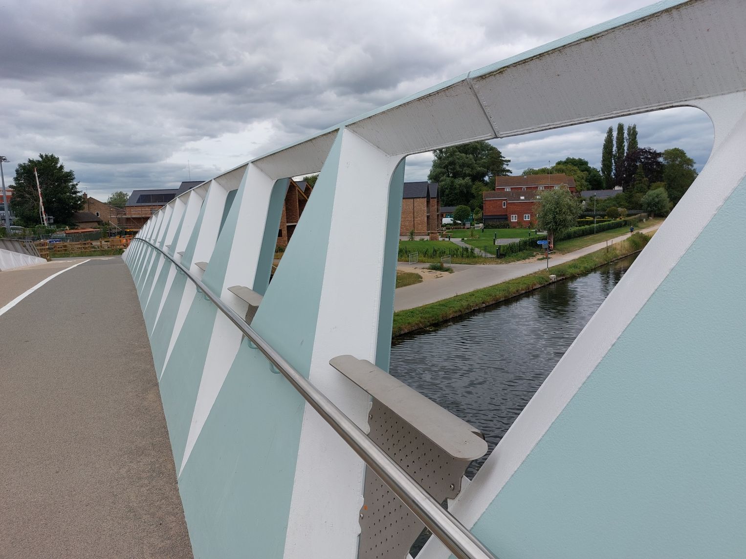
Once up onto the bridge, the answers begin to emerge. The bridge deck is segregated between cycle and footways, which is probably sensible given the way that some Cambridge cyclists like to whizz around. This explains the asymmetry in the parapet design. There are perforated stainless steel plates filling the triangular openings in the trusses, folded over at the top to provide a stiff upper edge. On the pedestrian-only side of the deck, that edge is 1.1m above deck level, and it is 1.4m on the cycle side.

My feeling of joy in the bridge design began to take a nose-dive at about this point. The first thing that drew my attention was a gap in the top chord of the truss. Err, sorry, "truss". There are regular narrow gaps in this element, with what look like little dowel bars hidden away inside. This seemed odd. For the non-engineers amongst my readers, the top chord on a single-span truss carries a compression force, while the bottom chord (mysteriously absent here), carries tension. It's not easy to carry compression if you leave a gap though!
There seem to be two possibilities for how this bridge works structurally. One is that the dowel bars do indeed transfer compression, but the gaps are needed to reduce bending restraint in the upper structural member i.e. to act as "pins" allowing local rotation. I can only say that I wouldn't do it like that, and I don't think this is the case anyway.
The other possibility is that this is not a truss at all, and that the bridge is in fact a box girder with a curved belly - and the triangulated "truss" elements are just an incredibly expensive way to support the parapet handrails. This is what I think is the case, and I suspect it's an artefact of the design-and-build process i.e., a compromise added to make the structure easier to analyse, design or fabricate. No gaps are shown on the planning consent drawings.
I wouldn't like to be the maintenance engineer charged with trying to paint the faces inside each gap at some point in the future.
The second feature of the bridge that drew my attention is the relationship between the parapet treatment within the length of the "trusses", and its treatment beyond them. The upper edge of the truss curves down at its ends, which is structurally rational for a truss and visually coherent in any case. However, it curves down below the height required for parapet containment of pedestrians and cyclists. The upper edge line of the parapets therefore passes above the upper edge line of the "trusses" at their ends, resulting in a need for parapet elements very different in form to the perforated infill panels.
It's straightforward as a relationship between two intersecting lines, one curved relative to the bridge deck level, and one parallel to the bridge deck level. However, the detailing is quite awkward, and it feels like the parapet sections at the ends of the bridge are afterthoughts, with no obvious relationship to those in the middle.
Beyond the ends of the bridge, there's a classic bit of "architecture", that is the derivation of form from what is visually rational rather than structurally rational. This comes in the form of a series of concrete panels that continue the line of the "truss" curve downwards. There is no longer any force to be transmitted in the structure (we're off the end of the bridge at this point), but it results in yet another variation in the parapet form. It's lovingly detailed, yes, but a consequence of the formalist geometry of the bridge composition, not of anything else.
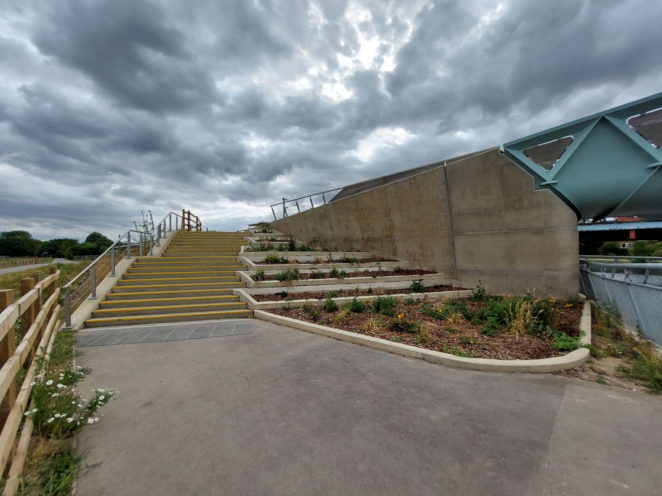
At each end of the bridge, there is a staircase down to the riverside footpath, wrapped around stepped landscaping. The bridge's concrete wing walls are a little austere, but they were remarkably free of graffiti when I visited.
Despite everything, I was surprised to find I still liked this bridge. Even if the structural form is seriously compromised, the visual identity remains attractive.
However, in a time when the evangelists for Net Zero are pushing us to make more efficient use of material (to "use less stuff", in the words of one), this probably isn't a design that anyone should wish to copy. One lesson that could be learned from this bridge is that a form that is visually attractive may be problematic to deliver if it isn't rooted directly in a sensible structural form (here: the lack of bottom chords to the truss).
If the Abbey Chesterton Footbridge tells us anything else about how to deliver a good quality bridge, an alternative lesson is simply about how to avoid letting the procurement process leading to compromise. With the increasing impetus towards decarbonisation and the pressing need for higher quality design more generally, it's clear we really need to find better ways to connect and incentivise the various participants in the construction supply chain.
Further information:


3 comments:
It's always a pleasure to see you back.
My guess: probably one more victim of redesign due to inflation and stress in logistic chains in the last couple of years. A similar image to the one accorded with the client or won in a competition has to be kept while reducing costs or even changing the main structural materials, often leading to these kind of "dishonest" designs.
It reassuring to see a fellow bridge engineer commenting that they cannot see a sensible structural logic in a structure. I sometimes think it is just me that as not as smart a bridge engineer as I think!
I would think there is enough steel in the curved bottom corners for a bottom chord if you include the deck plate too. The NR LMZ footbridge relies on the deck in this way. Though would not think the dowel detail then necessary.
Post a Comment